Robert from Canada found my old thread JBL 2226H 30 hz "horn" i built and asked for plans.
I have been working on a new sub design some time now and with very little work I have incoporated the improvements in a new JBL 2226 design.
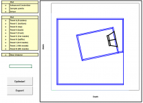
Enclosed is the 3d-drawing in step format. The cut sheet is missing, but I will make one when the design stabilizes.
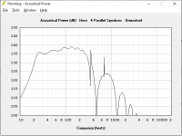
The zip also includes a Hornresp record. I need to add values for the front chamber.
I can make changes to the design quite easliy. I generate the drawing from a script. The script also generates the Hornresp record.
If you want a longer horn (goes lower), just add some on the depth or hight. If you want a bigger back chamber, just add some width.
Thickness and bracing are easily changed as well.
I have been working on a new sub design some time now and with very little work I have incoporated the improvements in a new JBL 2226 design.
Enclosed is the 3d-drawing in step format. The cut sheet is missing, but I will make one when the design stabilizes.
The zip also includes a Hornresp record. I need to add values for the front chamber.
I can make changes to the design quite easliy. I generate the drawing from a script. The script also generates the Hornresp record.
If you want a longer horn (goes lower), just add some on the depth or hight. If you want a bigger back chamber, just add some width.
Thickness and bracing are easily changed as well.
Attachments

Hmm... that looks like a pretty easy layout to implement in on one of my BOXPLAN Excel workbooks. If I have some time this weekend I think I'll try to create one for it.
Hmm... that looks like a pretty easy layout to implement in on one of my BOXPLAN Excel workbooks. If I have some time this weekend I think I'll try to create one for it.
Wonderful! Perhaps you could double-check the generated Hornresp areas and lengths?
Last edited:
Yup - that's what the BOXPLAN workbook would do. It will chuck out all the Hornresp params based on a particular physical layout of the box.

Great!
The bracing is pretty important I have realized, especially at the horn throat.
Two hornresp sections are needed for the first section of the horn since it is an offset driver. There are two Hornresp sections left, but three real sections. At these corners I can do an area step. In my script I can choose if the first or second corner from the mouth is such a transition. I have not used it in this design, but the change from 2 to three braces in the first corner from the throat made me choose this corner for a transition.
Last edited:
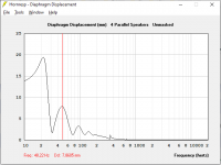
A few simulations of 4 cabinets at maximum cone exursion
😱
 ! Theres a Beautiful creature, almost as if the inside box is a handle. Its crooked, because you reach in, wind up the clock spring, and bam! ———-> a burst of impedance matching horn shape gets released.
Yup - that's what the BOXPLAN workbook would do. It will chuck out all the Hornresp params based on a particular physical layout of the box.
My input parameter are:
- Outer width
- Outer depth
- Outer height
- Material thickness
- Bracing thickness
- Exit area
- Exit angle
- Driver diameter (offset is another 2 mm)
- Which corner to do an area step (first or second from mouth)
- Ratio of first corner area step.
- Ratio of second corner area step
- Number of vertical braces at mouth
I have added VTC to the hornresp record. I don't have a 2226 at hand so the value is aproximate.
This is new version of the drawing with remade driver mounting.
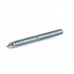
The driver should be mounted using what we in Sweden call a skruvstift. Picture enlosed.
The driver is boxed with new bracing using 0.5 mm clearance. Apart from stiffening the mounting, the driver should be protected from those bolts during mounting.
This is new version of the drawing with remade driver mounting.
The driver should be mounted using what we in Sweden call a skruvstift. Picture enlosed.
The driver is boxed with new bracing using 0.5 mm clearance. Apart from stiffening the mounting, the driver should be protected from those bolts during mounting.
Attachments
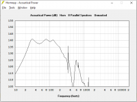
I love the fold it looks a lot easier to build than other horn subs. I had a go at simulating it with the 15DS115 as a higher performance driver and got the attached results. Although maximum output has gone up 6dB the response has a lot of ripple, any ideas on how to fix this?
Attachments

The 15DS115 is far to powerful for this design. The Q is too low and the BL is too high. This driver would work very well in a hyperbolic horn. Much harder to build though.
This design is a parabolic horn with a very small exit area. It has more in common to a quarter wave pipe than an exponential horn. Look for a driver with TS parameters closer to JBL 2226.
This design is a parabolic horn with a very small exit area. It has more in common to a quarter wave pipe than an exponential horn. Look for a driver with TS parameters closer to JBL 2226.
any ideas on how to fix this?
8 in paralell. And a DSP to fix the remaining ripple.
Attachments
a horn for drivers that don't like horns
Right, ideally we want WG drivers, i.e. > vented max flat = > ~0.403 Qts'
Qts' = Qts + any added series resistance [Rs]: Calculate new Qts with Series Resistor
The 15DS115 is far to powerful for this design. The Q is too low and the BL is too high. This driver would work very well in a hyperbolic horn. Much harder to build though.
This design is a parabolic horn with a very small exit area. It has more in common to a quarter wave pipe than an exponential horn. Look for a driver with TS parameters closer to JBL 2226.
can you help me understand how the specs of a driver can make it more or less suited to a different shaped horn like hyperbolic or parabolic as you have said? up until this i thought a driver was suited for a horn loading or not , not that im completely understanding how or why one does fit that criteria yet but that was my understanding.
Getting there..
Just need to map out the path now and choose the optimization points...
Great news!
What are you going to call it?
- Home
- Loudspeakers
- Subwoofers
- The return of the JBL 2226H parabolic horn