can you help me understand how the specs of a driver can make it more or less suited to a different shaped horn like hyperbolic or parabolic as you have said? up until this i thought a driver was suited for a horn loading or not , not that im completely understanding how or why one does fit that criteria yet but that was my understanding.
For a traditional exponential or hyperbolic horn you look for a driver with the following characteristics:
- Low Qes
- High Bl
- Low Le
- Low Mmd
- Strong cone
For a quarter wave pipe (and tapped horn and my parabolic thing) you want a driver with
- Medium Qes
- Medium Bl
- Low Le
- High Mmd
- Strong cone
Why it is so, I really don't know, but I will get the cavalry 🙂
Im no expert, just an enthusiast, but it would seem the lightweight cone and moving mass could use the narrow CSA and increasily bigger air column to keep that motorforce in check, otherwise it could be w bit ‘hyper’ or indulge in excess?
While the other has a moving mass with momentum to keep it smooth, while probably a lower Fs and Qts combo for a lower FB potential and the lazy air column shaped for the deep pipe or BLH like air column shapes that suit it?
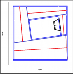
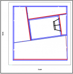
Its a really nice design. Convenient shape with the square inside a square, but tilted.🙂
While the other has a moving mass with momentum to keep it smooth, while probably a lower Fs and Qts combo for a lower FB potential and the lazy air column shaped for the deep pipe or BLH like air column shapes that suit it?
Its a really nice design. Convenient shape with the square inside a square, but tilted.🙂
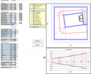
I had a go at simulating it with the 15DS115 as a higher performance driver
I did a few simulations with the 15DS115. I tried various alternative shapes using my parabolic layout. I could not find a better layout than the 2226.
I also made a Hornresp optimized horn. And in a horn optimized for JBL 2227. The 2227 is much better. Quite surprisingly.
For a traditional exponential or hyperbolic horn you look for a driver with the following characteristics:
- Low Qes
- High Bl
- Low Le
- Low Mmd
- Strong cone
For a quarter wave pipe (and tapped horn and my parabolic thing) you want a driver with
- Medium Qes
- Medium Bl
- Low Le
- High Mmd
- Strong cone
Why it is so, I really don't know, but I will get the cavalry 🙂
You realise that Tom Danley's first tapped horns used the drivers that you list as being useful for horns.
Great news!
What are you going to call it?
Haven't decided yet.
The Optimization process turned out to be surprisingly simple after I mapped out the path. Now it's just to clean up some of the calculations and the layout of the workbook, and it should be good for use.
Note, with a simple tweak this can be converted to an approximated conical or exponential horn. Might look into that over the weekend.
Attachments
Haven't decided yet.
The Optimization process turned out to be surprisingly simple after I mapped out the path. Now it's just to clean up some of the calculations and the layout of the workbook, and it should be good for use.
Note, with a simple tweak this can be converted to an approximated conical or exponential horn. Might look into that over the weekend.
It is possible to change the area at two corners. And still be Hornresp compatible.
You realise that Tom Danley's first tapped horns used the drivers that you list as being useful for horns.
The first or the second list?
The first list.
The drivers that give the greatest difference in efficiency versus an equivalent sized vented box in a tapped horn are usually the lighter high BL traditional horn drivers.
The drivers that give the greatest difference in efficiency versus an equivalent sized vented box in a tapped horn are usually the lighter high BL traditional horn drivers.
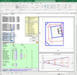
It is possible to change the area at two corners. And still be Hornresp compatible.
I'm not sure I understand what you mean.
Great work Brian, I will check it out. I am particularly excited by the possibility of other flares so I can try to maximize output for PA use.
I'm not sure I understand what you mean.
Attachments

It says v0.1 BETA, but I think it's just about finished, unless someone turns up a bug in the workbook when they play with it.
On my site, it's the BOXPLAN-PARAH workbook.
Great work Brian!
I will make free CAD drawings for any horn using hifi class drivers or pro drivers out of production. Just create a new thread and PM me.
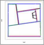
Ah, a stepped horn?
It should be possible, but require quite a bit more work. The challenge is defining exactly where the "step" takes place in the model of the physical layout. It's possible that some path length errors might be introduced in the process.
Doing it that way is probably going to introduce a few path length inaccuracies, resulting in the built horn having a slightly higher Fc than the Hornresp model predicts.
The key is to end up with a Hornresp model that has the same (or less) net volume than the box design suggests it should be. If you have a folded design that has the same net volume and path length as the corresponding Hornresp model, then it's likely the effective path length is going to be a little shorter, because each rectangular fold in the horn results in a slight shortening of the path.
That's the lesson that I learned with my POC2 build, which was designed using a simple centerline method for determining the path length. Net volume and path length matched the Hornresp sim, yet Fc turned out slightly higher than expected. Now I use the Advanced Centerline method, which produces measured results that are much closer to what the sim suggests they should be.

I think letting the actual Fc do what it will anyhow (within reason)and concentrating on the wall to wall standing wave vs pressure wave exits result in segments of (harmonic intervals) and folding to support a ‘stepped pipe expansion’ intervals of wanted LP of the phase in steps in sound towards the opposite origins will show what Harry Olsen might suggest. Kindof what ‘offset driver entry’ can support when used for the place it sits in the (middle) of The affective pipes ‘flow’ phase cycle vs straight length of physical pipe to a closed end making 3 parts into 2 -driver- 2 if interpreted as such a course phase inverter’.
But heres the reference for driver specs that might suit a pipe or a stepped horn version. (Your post in the hornresponse thread might be answered in here), I hope i get the link to function and helpful in cut/paste:
Elements of acoustical engineering : Olson, Harry Ferdinand, 1901- : Free Download, Borrow, and Streaming : Internet Archive
Last edited:
Doing it that way is probably going to introduce a few path length inaccuracies, resulting in the built horn having a slightly higher Fc than the Hornresp model predicts.
How about this way then?
Attachments
- Home
- Loudspeakers
- Subwoofers
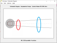
- The return of the JBL 2226H parabolic horn