SY said:I'll confess: I'm over 350 in people years.
Attachments

SY said:I'll confess: I'm over 350 in people years.
That's a phrase I used to use after every bear market -- "Dog Years" vs "People Years".
SY et al,UL just has too much input capacitance to do current limiting this way.
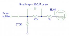
When using the EL84 in UL (or especially in full triode mode) you’ve raised a valid concern about dragging down bandwidth with the large current limiting resistor and the larger Cpg relative to pentode mode. Maybe you could try this. Add a separate grid stopper (<<grid current limiting resistor) to keep the tube out of falsetto mode, and bypass the 47K grid limiting resistor with a tiny cap, maybe in the neighborhood of 100pF (just a wild guess). At high frequencies, this would create a low-attenuation capacitor divider with the input capacitance of the EL84. With the right value of the small cap, the BW could be significantly extended, and whole-amp stability would be enhanced so long as something else like the OPT is setting the dominant pole.
Now this little cap will store charge during overload, which was your original concern, but the energy will be minuscule and the short time constant means that it will recharge within tens of microseconds (setting the pole just above the audio band). So maybe there is a way to have your cake and raise insulin levels with it too. I can’t find a data sheet value for Cpg for the triode-connected EL84. UL-mode Cpg will be part of the way between the full unscreened triode Cpg and the 0.5pF spec for pentode mode. IIRC, the Dyna 35 OPT has a low UL tap – was it about 27%? So I’m merely guessing at a value for the small cap here. Maybe a dumb idea or one already set forth…
Attachments
Brian, you're talking about something like the tricks in the old Citation amps? That seems like an excellent approach.
The only downside I see off the top of my head (besides power) is the necessity to regulate B+ or otherwise have a very stiff supply and the need to provide for idle current adjustment.
The only downside I see off the top of my head (besides power) is the necessity to regulate B+ or otherwise have a very stiff supply and the need to provide for idle current adjustment.
Well, I hadn’t recalled any particular amp, but now that you remind me of it, I have seen lead compensation applied to grids using a similar approach. Sometimes a shunt R will follow the series R so that at low frequencies there is a divider loss. At higher frequencies the cap makes a zero and then a pole at just the right frequencies to make the phase shift work for improved stability. But in your case the value of the bigger resistor is determined by a current limiting requirement, there is no shunt R, and added cap is there to keep the EL84 capacitances driven by a low impedance at high frequencies. Yes, very similar though.
I’m missing your point about B+ regulation (for what versus what?). Maybe I’m dense today.
I’m missing your point about B+ regulation (for what versus what?). Maybe I’m dense today.
Giaime said:Remember to use a noninductive 47kohm 😉
It's just not possible to get an inductive 47k.
SY, OK (answering part of the question myself), you had used screen adjustment to set the bias for the pentode mode and with UL that option is gone. Hmmm. I see the dilemma. Boy, fixed bias has some real advantages, doesn’t it? Maybe some simple adjustable variant of that under the 270K resistors?
Well, with adjustable B+ regulation, you can set the idle current. And in a balls-out version, I might want to do just that. OTOH, if I were going balls-out, I'd probably use a source or cathode follower to drive the output stage.
EC8010 said:
It's just not possible to get an inductive 47k.
They aren't wirewound 47k, you're right, but metal film for this aspect is worse than carbon comp. Trick learned from ham guys, when paralleling a series grid resistor with a cap (useful in regenerative radios) always use a c.c. resistor.
Perhaps use the heater supply to make DC if it’s not DC heated already. Put a CCS diode in series with four red LEDs across that DC voltage. Ground the junction of the two middle LEDs. This gives you shunt regulated +/- 3.4V supplies. The heaters won’t care about this slightly offset ground reference. Now put a pot across each of the +/- 3.4 volts supplies so that you can lift or drop each 270K grid resistor by anywhere from -3.4 to +3.4 volts. Add the usual safety resistors in case the wiper goes open. That grid adjustment range ought to be enough to counteract any EL84 imbalance. Since this is weird fixed bias with your cathode LED lift, we don’t need a large negative bias voltage, just some tweaking around zero volts. Should the bipolar 3.4 V supply fail, the tubes won’t self destruct because they’ve still got substantial Vgk bias. Added complexity? You bet. Maybe not in the spirit of your project. Worth it for UL? Maybe.
OK, correction on my prior post. So much for day-dreaming out loud. I see that SY has wisely lifted the heaters by 20% of B+. So we can’t anchor the heater supply to near-ground as I had proposed for making a small bipolar biasing supply. We have several choices then if we want to go UL and be able to adjust the bias:
1.) Find another way altogether to adjust bias (but let’s not give up so easily).
2.) Use tubes and voltages that can handle a near-ground referenced heater supply. Then use the suggestions in my post above.
3.) Use the 20% B+ floating heaters, and AC couple the heater secondary windings to a low-current DC supply that is near-ground referenced as above. This adds a couple of moderate-size caps to the mix.
4.) SY used a second power transformer for the higher B+ of the input stages. If the one that you find happens to have an unused low voltage winding, perhaps for a heater, this can be used to create the bipolar supply. The current demand is very small and VA burden on the transformer will be negligible.
You only need one such series-LED shunt bipolar supply for both channels (for all 4 EL84s). You can place either 2 or 4 bias adjustment pots across the LEDs, depending on whether you want to adjust the grid bias on just one side of each PP pair for balance (but not adjusting total current) or on each individual tube for control of both balance and absolute current. My prior post was not clear on that.
It’s so easy to depart from simplicity. It’s a battle I’m always fighting, And often losing. SY’s concept was for something easy and simple. The freedom from blocking is very desirable. Is it worth adding this added complexity to enjoy the benefits of UL and still use LED cathode bias at the same time? I think it might be, but you may not.
Problem is that this is all designed as an interacting system, not a bunch of disconnected parts. That's just the way I do things. And it hangs together, both on a design-esthetic and sonic basis. Don't let the pentodes put you off!
I think that to do what you want to do, you have to take a from-the-ground-up approach: cathode followers, adjustable grid bias, and probably a diff amp input stage. The last would allow local feedback loops from the output tube plates. It's a more complex way to go, but there might be some sonic benefit. Note the use of the word "might." I'm not as happy with my other amps at the moment...
I think that to do what you want to do, you have to take a from-the-ground-up approach: cathode followers, adjustable grid bias, and probably a diff amp input stage. The last would allow local feedback loops from the output tube plates. It's a more complex way to go, but there might be some sonic benefit. Note the use of the word "might." I'm not as happy with my other amps at the moment...
SY,
Of course I respect that you've put together a well-thought through and holistic pentode design. You mentioned the muscularity of your pentode's sound, and I'm not surprised by that, a pentode trait. But when the subject of UL came up, well, you got me (and gingertube) to thinking. I would like to get lower than a 2 ohm output Z if possible. Since I've got a SCA-35 awaiting my further attention, and since you’ve set me down a new path illuminated by red lights - I started thinking about how to use your design with its grid current limiting and LED cathode bias advantages, while hanging on to UL mode. Before reading your article, I was going to use 40mA CCSs in the EL84 cathodes with large bypass caps, not ideal under overload. I’ve got a big bag of red LEDs. I think I’ll use them. I may even use the much-maligned 12AT7 after your favorable experience with it. So basically I’m coming around to your entire design, but wanting to try UL for its linearity and lower output Z. Or at least wanting to find out how it does relative to pure pentode. This tossing about of ideas is in the spirit of the DIY forum after all.
So I think that a UL variant of your “red light district” design MAY be feasible and practical after all. Option 4 above would be best. It should not require a wholesale redesign from the ground up. The few added parts would not force this into a “balls-out” approach. We won’t know until someone tries! I wish I had more time these days for the workbench. I’ve already got too many projects in queue…
Me, too. Way too little time. Work. Travel. Small child. Obligatory Sunday liver-bashing.
I'd love to try it myself; it's a low-parts-count and elegant way to do it. But just my opinion, if you're going to do it, then do it all the way and try to get it working with a triode. If low source impedance is a desiradatum, I'd rather rely on a pair of low resistance anodes than the vagaries of all the coupling variables in a tapped high impedance primary. The power loss compared to pentode is probably 3-4dB.
I'd love to try it myself; it's a low-parts-count and elegant way to do it. But just my opinion, if you're going to do it, then do it all the way and try to get it working with a triode. If low source impedance is a desiradatum, I'd rather rely on a pair of low resistance anodes than the vagaries of all the coupling variables in a tapped high impedance primary. The power loss compared to pentode is probably 3-4dB.
Yes, it would be fun to have an EL84 amp that could be easily reconfigured for direct comparisons of triode, UL and pentode modes, all the while using the same front end, power supplies, even the same glowing bank of LEDs. The little +/-3.4V supply I proffered could be useful in all three modes. The input compensation RC might have to be jiggered with as gains and BWs shift about in the three modes.
Maybe that ought to be my SCA-35’s raison d'être.
Careful with that liver bashing
Maybe that ought to be my SCA-35’s raison d'être.
Careful with that liver bashing
Careful with that liver bashing
Don't worry, we're professionals.
I'm anxiously awaiting shipment of some James transformers. Some crude tests with old LS-series iron indicate that the limiting factor in performance is the OPT. On paper, the James look good and there has been a lot of favorable comment about them. Lundahl or Magnequest are not in my financial future.😡
Given my modest goals for the SCA-35 redo, I will be content to stay with the iron that is already in the SCA-35 box, including the merely OK OPTs. Restraint from me? Who would have thought...
It will be interesting to hear what you think of the fancy iron coming your way. Any thoughts of Plitron toroids? Or maybe cheaper toroidal power trannies as OPTs?
It will be interesting to hear what you think of the fancy iron coming your way. Any thoughts of Plitron toroids? Or maybe cheaper toroidal power trannies as OPTs?
Plitron- thought about 'em, but the money has to go elsewhere, like paying the mortgage. I still worry about how sensitive those are to small levels of DC imbalance; they could be quite interesting for my big class B amp.
- Home
- Amplifiers
- Tubes / Valves
- The Red Light District - another PP EL84 amp