Was it this one, or did we do another?
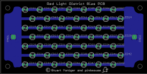
That one is missing the mouse on the silkscreen 😀
dave

Toner ready please!
This will be an interesting experiment for a preamp I'm almost finished.....
You know, way back I used that pic that you posted to make the regs for my rld build...... but made a balls of it! Learned a bit since then........ a bit. 🙂
This will be an interesting experiment for a preamp I'm almost finished.....
You know, way back I used that pic that you posted to make the regs for my rld build...... but made a balls of it! Learned a bit since then........ a bit. 🙂
...Learned a bit since then........ a bit. 🙂
Glad someone has!
Hey Pinkmouse,
When you zoom out the image it grows to about 3 1/8 x 6 1/4. Is that the actual size for the board? Since I'm going to Paint this board to etch it I can just photocopy it. I'm not familiar with the other types of files, except maybe the Acrobat PDF.
Kevin
When you zoom out the image it grows to about 3 1/8 x 6 1/4. Is that the actual size for the board? Since I'm going to Paint this board to etch it I can just photocopy it. I'm not familiar with the other types of files, except maybe the Acrobat PDF.
Kevin
Thanks Sy,
I just ordered the parts from Digikey. For the 7591A amp I'm going to use fixed bias using an LM337. I'm going to put heat sinks on all the transistors. Time to learn how to make PCB.
Thanks again, Kevin
I just ordered the parts from Digikey. For the 7591A amp I'm going to use fixed bias using an LM337. I'm going to put heat sinks on all the transistors. Time to learn how to make PCB.
Thanks again, Kevin
Hey Pinkmouse,
could you post the eagle files? I can make them very easily with university resources. (your tax dollars at work)
Thanks
-Moose
could you post the eagle files? I can make them very easily with university resources. (your tax dollars at work)
Thanks
-Moose
what i do with my amp build is to wire up the secondary side first......the plate leads are soldered lightly to tube pins....
there is a 50-50 chance you'd get it at first go....so that in case of motorboating, i simply reverse the plate leads, dressing it up and cutting for final soldering to tube pins....
Yesterday I ran some diagnostics with oscilloscope. Phase is ok, grounded terminals. No motorboating. Yes! So feedback connected - checked. Found one cathode resistor not well soldered! The other channel connected. Now it works great. I rused twisted wires instead of shielded wires I had used before. Hum is 0.4 mV left channel, 1.5 mV right one.
Yesterday I ran some diagnostics with oscilloscope. Phase is ok, grounded terminals. No motorboating. Yes! So feedback connected - checked. Found one cathode resistor not well soldered! The other channel connected. Now it works great. I rused twisted wires instead of shielded wires I had used before. Hum is 0.4 mV left channel, 1.5 mV right one.
congratulations......😀
Excellent!
With careful attention to heater wiring and dress, you should be able to get the noise in both channels down to 0.2mV or better. Though 1.5mV isn't bad (I assume it's mostly hum?)- that's 80dB down from full output.
With careful attention to heater wiring and dress, you should be able to get the noise in both channels down to 0.2mV or better. Though 1.5mV isn't bad (I assume it's mostly hum?)- that's 80dB down from full output.
i bias the heaters with dc, anywhere from 40volts to 90volts using voltage dividers taken off the B+, no hum issues for me so far....
- Home
- Amplifiers
- Tubes / Valves
- The Red Light District - another PP EL84 amp