And heres tonights progress:
front view with the valves sitting in place:
And underneath:
The main PTx is on the top along with the 2 output transformers. Underneath is the second PTx along with the 2 chokes.
Rear view:
Any comments?
Fran
front view with the valves sitting in place:
An externally hosted image should be here but it was not working when we last tested it.
An externally hosted image should be here but it was not working when we last tested it.
And underneath:
An externally hosted image should be here but it was not working when we last tested it.
The main PTx is on the top along with the 2 output transformers. Underneath is the second PTx along with the 2 chokes.
Rear view:
An externally hosted image should be here but it was not working when we last tested it.
Any comments?
Fran
Hi Fran,
What output transformers did you choose? Looks like you have enough real estate under your chassis to build two versions at once.
Pete
What output transformers did you choose? Looks like you have enough real estate under your chassis to build two versions at once.
Pete
Fran, beautiful work.
See what you can do about getting airflow from bottom to top (convective) of the EL84s. Some artfully done holes, arcs, whatever, you just need air to be able to be drawn up from the bottom.
See what you can do about getting airflow from bottom to top (convective) of the EL84s. Some artfully done holes, arcs, whatever, you just need air to be able to be drawn up from the bottom.
RE: Output Tx:
Pedroscova, the ones I used were from triode electronics (?). I can't remember exactly how much they were but not that dear, amybe about $30 ea. The main PTx and chokes came from elletro novarria in Italy, very cheap and seem to be OK, although the primary is rated as 220 (as per China) whereas my mains line usually runs about 235V or so. the 6.3V winding unloaded comes out at 6.7V. 240V sec comes out at 248-250 again, unloaded.
RE: PCB:
thats a lovely PCB, but well beyond the single sided marker and etch agricultural system that I would be implementing! This is a case where backwards is really forwards! (Would the guy have some for sale or spare do you think SY?)
EDIT: does the pinout on the tip50/lm317 and pot look right to you (ie on my "PCB")?
RE: Cooling:
The plan (!) is to use 2 of those fan cages (you know the chromed grilles) appropriately placed on the bottom so that the red LEDs provide a bit of glow underneath the amp. I intended to drill a series of holes around each of the valves, but now thinking about your suggestion, an arc of holes either side of the arc of the tubes might be nice.
I find myself at the stage where I'm starting to get out of my depth a little. I know I just need to "be cool yolanda" and take it one bit at a time though. The next job is to mount the second PTx underneath properly and drill the holes for the tube cooling. After that I think most of the drilling should be done and I can finish the casework. Then go back and fit the hardware and start wiring.
I think I will do PCB/breadboards for the B+, regulators, LEDs and hopefully just P2P the rest of it.
The finished case is to match my aikido:
An externally hosted image should be here but it was not working when we last tested it.
woodturner-fran said:RE: PCB:
thats a lovely PCB, but well beyond the single sided marker and etch agricultural system that I would be implementing! This is a case where backwards is really forwards! (Would the guy have some for sale or spare do you think SY?)
Thanks for the compliments, but I just design 'em, I let others do all the real work. 😉
edit: And I have a team of very talented advisors to save me from stupid mistakes too!
Nice amp BTW! I still have a bag of 100 LEDs lying around looking for a home...
Hah, I was just looking you up to see if I could email you!!
My comments RE the PCB aren't actually worth the pixels - I wouldn't really know, but as I said it looks good!
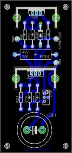
Actually, when I looked at it again, its actually single sided. Would this be right:
Q201 - TIP50
IC201 - LM317
C201 - 20uF/450V
ZD201 - 12V zener
R201 - 10K
R202 - 100R
R203 - 47R
R204 - 56K/3W
R205 - 200R
R206 - 180K
R207 - 4R7
R208 - 100K POT
If thats all OK I might try and knock one up... provided thats Ok with you of course.
Fran
My comments RE the PCB aren't actually worth the pixels - I wouldn't really know, but as I said it looks good!
Actually, when I looked at it again, its actually single sided. Would this be right:
Q201 - TIP50
IC201 - LM317
C201 - 20uF/450V
ZD201 - 12V zener
R201 - 10K
R202 - 100R
R203 - 47R
R204 - 56K/3W
R205 - 200R
R206 - 180K
R207 - 4R7
R208 - 100K POT
If thats all OK I might try and knock one up... provided thats Ok with you of course.
Fran
That mostly sounds correct, though I can't check for certain at the moment as the files are on another computer. I think we used a different transistor though.
OK,
so besides fitting a new cart to my TT, heres what else I did tonight:
I think it should all work OK. I suppose I won't really know until I fire it up! (and thats a bit away yet).
Now what would be really handy is if something similar was done in a similar single sided manner for both of the B+ rectification sections (harumph, cough etc)!
SY/pinkmouse - I don't have heatsinks as big as the ones spec'd on that PCB. Would smaller ones do OK?
Fran
so besides fitting a new cart to my TT, heres what else I did tonight:
An externally hosted image should be here but it was not working when we last tested it.
I think it should all work OK. I suppose I won't really know until I fire it up! (and thats a bit away yet).
Now what would be really handy is if something similar was done in a similar single sided manner for both of the B+ rectification sections (harumph, cough etc)!
SY/pinkmouse - I don't have heatsinks as big as the ones spec'd on that PCB. Would smaller ones do OK?
Fran
Regulating pentode plates really doesn't buy you much. It's not zero, but looking at plate curves, it's pretty evident that the major gains are gotten by regulating the screen supply.
Heat sink: I think I talked about it in the little article in Bas's webzine, but if I didn't, you can do the thermal calculation yourself for a candidate heatsink. You know your input voltage and output voltage, so you know the voltage drop across the regulator. Get the max screen current under full drive for the output tubes. Now you know the power needed to be dissipated. Yes, 10 or 11 volts will drop across the LM317, but let's ignore that- it just builds in a bit of a safety factor here.
Now, the heatsink will have a thermal resistance rating in ohms per watt. Add 2 degrees C/watt to it to accommodate the thermal resistance between the transistor and the heatsink. This gives you the total thermal resistance (degrees C per watt) between the transistor and the rest of the universe. Now if you multiply this by the power to be dissipated in watts, you'll get the temperature rise above ambient. 55-60 degrees C at the heatsink is about as high as I like to go for the sake of reliability.
I've been laying out some of the wiring on paper to get my head around it (I understand the principles fairly well, but converting the schematic on paper to reality I need to work at).
I have a question:
In the schematic, the feedback is brought back from the output Tx via a shielded cable to the cathode of the driver half of the 12AT7 with a 6K8 resistor to the cathode. This is shown as coming from one of the taps of the output Tx - I take it this is just shown this way for simplicity and that if you wanted you could also bring feedback from the other tap as well? Or can you only connect to one tap at a time?
No. 2:
The shield of the cable is connected at one end to the common of the output Tx, and at the other end it is connected to ground. But it looks like the shield and the cable from the tap of the Tx are joined together? ie centre conductor + shield are joined, then sheild is connected to ground and the centre conductor goes to the cathode via 6K8.
Do I have that right?
Fran
1. Yes, you could use a different tap, but you would need to change the size of the feedback resistor. IIRC, I used the 16 ohm tap; the 8 ohm tap will have 71% of the voltage across it, the 4 ohm tap, 50%. So to move the resistor from 16 to 8 ohms, you would decrease it by a factor of 0.7.
Likewise, if I've misremembered and I used the 8 ohm tap, the voltage at the 16 ohm tap is 1.4 times higher. So to move it to the 16 ohm tap, multiply its value by 1.4.
But you can leave it where it is and just connect your speaker to the appropriate tap- it really doesn't hurt anything to do that.
2. "Right" end of the cable: center conductor to the transformer "hot" tap, shield to the common. "Left" end of the cable: center conductor to the 6k8 resistor mounted near the input tube, shield to the bottom of the input tube's cathode resistor (which should be at signal ground). This places the OPT's secondary common reference for feedback and the feedback insertion point right at the input tube.
Great, many thanks SY,
You have it shown as connected to the 8R tap, so for a 4R tap I would 4K7, right?
New question, this time on PS:
Heaters:
On schematic, the heater winding is centre tapped and this centre tap is connected to c. 1/4 of the B+2 supply. The 2 legs of the heater supply also have a pair of caps with the centre of the caps connected to ground. I remember you telling me this was to remove some noise from the supply.
Now my Q: My heater is not centre tapped. Can I just move the connection to the 1/4 of B+ from the heater centre tap (as shown on the schematic) to the centre of the 2 caps? So instead of going to ground, this connection would go to 1/4 B+?
thanks again,
(real progress being made!)
Fran
No, the two caps must go solidly to ground; that bypasses common mode noise induced by the switching spikes from the HV rectifiers, coupled to the heater winding. If you use their junction for the DC reference, the winding won't be biased upward as required, since the caps block DC.
You can make a virtual CT. Connect two 100R in series across the winding, then take their junction to the DC reference.
You can make a virtual CT. Connect two 100R in series across the winding, then take their junction to the DC reference.
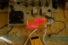
Well SY, you made me do it...the first red light magnavox console pull(6V6). 😎 It's in a 5x10 configuration that gives 19V. Unfortunately, my meter's mA function appears to not be working (0mA at the top of the 1R resistor)...or the amp's breaking the laws of physics, because it's making nice tunes.
I haven't tried the grid resistor yet because of gain concerns, and I had to drop the grid leaks from 470k to 100k, but I'm quite pleased with what I've heard.
pete
I haven't tried the grid resistor yet because of gain concerns, and I had to drop the grid leaks from 470k to 100k, but I'm quite pleased with what I've heard.
pete
Attachments
Great progress my end tonight. Chassis work is finished and the Tx are all mounted. I have the mains wiring done and also the heater wiring too. Next its power supply, maybe tomorrow night (although saying that has just put the kiss of death on it!
Exciting stuff!
Fran
Exciting stuff!
Fran
More progress! Power supply is wired up and all the voltages check out so far - with no smoke! I have 352V and about 330V, which I know is a little high, but thats without anything attached/load. I have to build the regulators yet. The voltage divider for the heater ground worked out nicely at 75V, just about 20% of the B+ and I had a 470uF/100V cap that I used for the heater string. I'm hoping it'll be OK at 100V when it should only be seeing 75.
I didn't check the 320V, but I have about 100mV of AC on the 350VDC, again, without any load applied. How does that sound to you guys? PS is as per the circuit.
I also have a fair bit of the circuitry around the sockets done. Its going to take a week for the LEDs to arrive from mouser. I wonder if I can wait that long, or will I succumb to temptation and use the ebay ones I have!
Oh yeah, this will be a "nest-o-snakes" model!
pics to follow
Fran
Some pics:
Regulators:
And the nest-o-snakes:
I just can't see how you could do it a lot neater either!!
And back up a bit in the thread someone talked about how you could fit in 2 of the amps in the the case - that space got filled up pretty quick.
So I think I just need to mount the regulators and wire them in, and then do the LED arrays. If all is well then it should be fire-her-up time.
I've brought each GND back to one point - star right? So, just checking here: The input grounds, various grounds from the circuit and power supply ground all join together in one point. Isn't this right?
Time to show my ignorance: the feedback circuit. I have the 8R tap of the Tx coming back via a 6K8 R for feedback. Thas OK and as per schematic. But if I was to use my speakers on the 4R tap wouldn't I need to bring a second feedback from that tap to the same point but with a lower resistor?
Fran
Regulators:
An externally hosted image should be here but it was not working when we last tested it.
An externally hosted image should be here but it was not working when we last tested it.
And the nest-o-snakes:
An externally hosted image should be here but it was not working when we last tested it.
I just can't see how you could do it a lot neater either!!
And back up a bit in the thread someone talked about how you could fit in 2 of the amps in the the case - that space got filled up pretty quick.
So I think I just need to mount the regulators and wire them in, and then do the LED arrays. If all is well then it should be fire-her-up time.
I've brought each GND back to one point - star right? So, just checking here: The input grounds, various grounds from the circuit and power supply ground all join together in one point. Isn't this right?
Time to show my ignorance: the feedback circuit. I have the 8R tap of the Tx coming back via a 6K8 R for feedback. Thas OK and as per schematic. But if I was to use my speakers on the 4R tap wouldn't I need to bring a second feedback from that tap to the same point but with a lower resistor?
Fran
- Home
- Amplifiers
- Tubes / Valves
- The Red Light District - another PP EL84 amp