I just finished reading this thread. I would like to try and build a red light district amp. I have one question for now. I own a pair of James 10K PP transformers. Will they work in this circuit?
Thanks
Chris
Thanks
Chris
They should be just fine, given that speaker impedances aren't exactly well controlled. Don't be afraid to experiment with output taps (true for the 8k p-p version as well).
i have found the post about the wattage of the resistors, sorry. but not everything is clear.
1)so i can use a 1/4w everywhere, exept where stated in the schematics ? also in the psu ?
2)can i use metal films in the psu or is that not done ?
i need to order an extra trannie, for the b2+ (screens)
and i will connect the 6.3v fillament on it too.
3)now i would like to know if that doesn't saturate the core or something like that; cause putting it at 25% of the b2+ is adding bias voltage to it ?
4)i would like to use a 5h 250ma for the b+1
but a 35h ? can i use a 10h at 50ma ?
thanx a lot SY, i'm gathering components.
until now: PRP resitors, kiwame grid stoppers, obbligato caps. copper teflon wire.
thanx
Use 2W for the plate and phase splitter resistors. The main voltage setting resistors on the screen regulators ought to be 3W or better; the trim resistors can be 1/2W. The rest are non-critical. I think I got all of the critical wattages indicated on the schematic.
No reason not to use metal film in the power supply. Metal oxide will also work well.
Floating the heaters will not cause any saturation- the DC goes through the divider string, not through the winding.
The 10H choke should work fine. I used 35H because I had a box of them.
Good luck!
No reason not to use metal film in the power supply. Metal oxide will also work well.
Floating the heaters will not cause any saturation- the DC goes through the divider string, not through the winding.
The 10H choke should work fine. I used 35H because I had a box of them.
Good luck!
thanx a lot. SY,
gotto shop forward, (not really my thing, looking all things together, but hé, no pain no game)
gotto shop forward, (not really my thing, looking all things together, but hé, no pain no game)
just a bump really to rise this thread!
I have started back at the amp after being sidetracked a bit by other stuff (I have been busy!!).
God but the casework is a pain.
A question for those who know:
I've done the test on my LEDs and when I hook it up to the 9V battery and 1K resistor I get 1.85 volts. Will I get away with this, or should I drop one from the series?
Fran
That's quite high for a red LED. Is this a newer high efficiency type?
You'll want to aim for 10.5V or so from the string. Of course the value you have either makes it too high or too low! Try 6 in series for the strings and see if the output stage biases up OK. If you can't get the idle current high enough with a screen voltage below 290-300V, take one LED out of each string.
I owe you a favor for the BOM work you did, anyway; if you send me your mailing address, I'll send you some red LEDs with a more normal drop.
Hi SY,
Isn't 1.85 V drop about normal for a red LED passing around 7 mA? The high efficiency types have an even higher drop last time I checked.
-Chris
Isn't 1.85 V drop about normal for a red LED passing around 7 mA? The high efficiency types have an even higher drop last time I checked.
-Chris
1.65-1.72 is a lot more common in "standard" surplus reds. I surveyed about 4 or 5 different ones for AC impedance and they were all within 20mV of 1.7. Morgan Jones saw the same thing, documented in Valve Amplifiers.
yep, they're the newer type, clear lens, bought cheapo offa ebay. Think it was about $10 for 100 incl shipping.
SY, thanks for your offer - but before I take you up on it I have an idea I have a couple of other LEDs out in the spares box. I need to check. Couldn't the 10.5V end point be adjusted a bit by varying the size of the resistor at the start of the string? If I'm right, thats there to limit current (OK?) but wouldn't it also vary the voltage a bit?
I think mouser has these back in stock as well:
mouser hlmp6000
If these are the right ones I don't mind springing the $24/100 for them. I have an order ready for mouser anyway.
*******************
I got the top plate more or less done tonight. I have an arrangement done where the main Tx is on top of the plate along with the output Tx and the second Tx and the 2 chokes are inside the chassis. This is gonna be one heavy amp to move around when its done!
Problem now is that its been so long since I was at this amp that I need to go back and read the whole thread again and also read the original article to make sure I understand it!
Fran
So, sitting here a bit bored today, and waiting on parts so I can do the Fisher 800B resto, I looked at the 7591 datasheet and the Fisher schem and I reckon there's potential for a 7591 based RLD amp. At the Fisher's op point Vg=16V, so 9/10 diodes in series should get close. The 12AT7 can also be swapped easily for the existing 12AX7 with some small mods.
There's plenty of room in the new case I'm building for it for the screen regs, LED arrays and some heatsinking (as well as the improved PSU0.
Worth a try for the bass bins in my modded KHorns (60-200Hz)
There's plenty of room in the new case I'm building for it for the screen regs, LED arrays and some heatsinking (as well as the improved PSU0.
Worth a try for the bass bins in my modded KHorns (60-200Hz)
Almost Finished RLD
It may not look pretty yet but I assure you I already put 50-100 hours on it and it sounds nice. I found that had to go down to 5 rows of HLMP6000 leds to get my EL84H's to bias up at a reasonable voltage.
Dont make the same goof I did. If you like to operate your unfinished amp upside down keep in mind that the voltage drop across the LEDS has some temperature dependence I was wondering for days why I had to keep chasing the bias set point for the first few hours of operation whenever I turned I on.
Am I the only person that just can't ever seem to straighten out those last few wires and put a box on anything?
Attachments
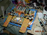
Oh great jumping jesuses!
That looks far more complicated than I thought it would be! I'll never wire all that up!
Fran
That looks far more complicated than I thought it would be! I'll never wire all that up!
Fran
but it gives me an idea:
Wouldn't it be a handy idea to build the screen regulators on a little PCB? Even if it was just the marker on copper-etch-clean method?
Has anyone done this? Would you like to share your design?!
Fran
Wouldn't it be a handy idea to build the screen regulators on a little PCB? Even if it was just the marker on copper-etch-clean method?
Has anyone done this? Would you like to share your design?!
Fran
OK,
here is a rudimentary sketch of a possible layout - it just follows the schematic but labels up the pins etc.
Could you look it over and tell me how wrong I am (I ain't good at all that stuff).
Fran
here is a rudimentary sketch of a possible layout - it just follows the schematic but labels up the pins etc.
Could you look it over and tell me how wrong I am (I ain't good at all that stuff).
An externally hosted image should be here but it was not working when we last tested it.
Fran
- Home
- Amplifiers
- Tubes / Valves
- The Red Light District - another PP EL84 amp