Here is poobah's text as rendered by my default TextEdit font. (i just had to change the text encoding to see the text is Japanese -- i had to cut & past it into TextEdit to make it big.
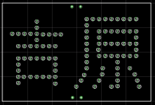
Is it 98 or 86 LEDs?
I have my 98 laid out, but this is much more interesting (harder to wire no doubt)
dave
Is it 98 or 86 LEDs?
I have my 98 laid out, but this is much more interesting (harder to wire no doubt)
dave
Attachments

It just gets better and better. Don't we have work to do?
My symbol shows the forth leg of the second symbol as concave down.
Planet 10's symbol shows the forth leg as concave up.
Could P 10's symbol mean, "going to"; and my symbol mean, "just been"? Speaking of the district, that is.
😕
My symbol shows the forth leg of the second symbol as concave down.
Planet 10's symbol shows the forth leg as concave up.
Could P 10's symbol mean, "going to"; and my symbol mean, "just been"? Speaking of the district, that is.
😕
Mhmm...the array works like a voltage source with low impedance from cathodes to gnd.
Good for recovery time indeed, but with this approach there is no way to set equal dc current in the OT primaries (which I suppose to be a good thing…).
Stuart, what do you think about the possibility of a mixed solution for the bias? I mean something like 6.8/8.5V from the array (four/five leds in series) and the remaining 5/3.5V with fixed bias, just to balance the dc currents…
Mark
The beauty of not using fixed bias is that one of the principle mechanisms causing blocking is eliminated. And, though I hesitate to mention this, it's a cheaper solution. At surplus, I bought LEDs for less than 5 cents. The 98 that I use for two channels ends up costing less than a high quality electroltic capacitor.
Mark raised an interesting question.
For you all, it's better to have zero DC flux on the output transformer or have those benefits in overload recovery?
And what could be the difference to bias the EL84 with a CCS?
For you all, it's better to have zero DC flux on the output transformer or have those benefits in overload recovery?
And what could be the difference to bias the EL84 with a CCS?
Very nice
Perhaps a warning might be necessary to prevent plonkers from introducing their, well, bits, into hot/high voltage places?
Perhaps a warning might be necessary to prevent plonkers from introducing their, well, bits, into hot/high voltage places?
Poobah, no, it's AB1.
And the currents are indeed balanced if you use reasonably matched output tubes. It is my experience that overload recovery is the single greatest factor separating really good amps from also-rans, much more so than the piddling imbalance introduced by 2 or 3 mils of mismatch (with toroidal output transformers possibly excepted).
Given how cheap TIP50 and LM317 are, if you're really worried about output stage balance, you could build a separate regulator for each screen.
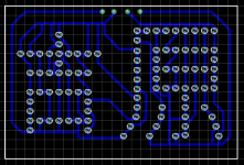
pinkmouse said:No copper yet... 🙂
Guess i shouldn't even try to wire mine up like that... i'll wait for boards.
dave
planet10 said:Guess I shouldn't even try to wire mine up like that... I'll wait for boards.
Actually, the wiring would be easy; it's the drilling that would be hard. However, an accurate PCB would make a good template for precise drilling of the chassis top plate...
SY said:
And the currents are indeed balanced if you use reasonably matched output tubes.
Yes...but this is not a solution if one of your goals is to make the amp cheap and even matched tubes can change their characteristics in time.
SY said:
It is my experience that overload recovery is the single greatest factor separating really good amps from also-rans, much more so than the piddling imbalance introduced by 2 or 3 mils of mismatch (with toroidal output transformers possibly excepted).
Sure, overload recovery is the greatest factor, but the current mismatch is the second one in push pull output stages, IMHO,...
SY said:
Given how cheap TIP50 and LM317 are, if you're really worried about output stage balance, you could build a separate regulator for each screen.
...so...this seems to me an elegant solution. A really good one Sy!
I like it... 😱
Mark
Yes, I suppose with the current going through them, a bit of neutral density acrylic (or whatever) in front would be a good idea to tone things down.
I was thinking that a lasercut logo like the decware stuff might be better. A piece of translucent glass on the inside could be used to dim the intensity a bit. I can see the bright red light in the corner causing a bit of concern in some areas.
Besides the glow of the tubes is lost in the flood of red
Besides the glow of the tubes is lost in the flood of red
Hmmm, maybe a "Close Encounters of The Third Kind" version will be cool. Circular chassis, with all those bright lights at the bottom 😀
I wonder what the voltage drop of a transluscent LED is 😕
I wonder what the voltage drop of a transluscent LED is 😕
- Home
- Amplifiers
- Tubes / Valves
- The Red Light District - another PP EL84 amp