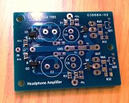
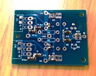
Some pictures, though there is a small soldering mistake.
Patrick
.
In the original post, there looked to be 8 active devices on the bar across the case, are those voltage regulators or?
Rectifiers.
Patrick
Ah alright thanks, that was a tad too many rectifiers 😛
By the way is it possible to simply substitute the output transistors with 2SA1943/2SC5200?
That's what I have quite a few of, not so much TO-220 BJTs
That's what I have quite a few of, not so much TO-220 BJTs
Too much capacitabce, and no where near as linear around bias.
Patrick
Ah well, I found a source for them from my usual shop. what about 2sc2240/2sa970 as a substitute for the input devices? Pouring over the datasheets tell me yes but 😱
> 2sc2240/2sa970 as a substitute for the input devices
If you can get genuine ones in BL grade, yes.
Also perfect for the original JLH version.
Patrick
If you can get genuine ones in BL grade, yes.
Also perfect for the original JLH version.
Patrick
> 2sc2240/2sa970 as a substitute for the input devices
If you can get genuine ones in BL grade, yes.
Also perfect for the original JLH version.
Patrick
My usual seller says he can match pairs of BL grade for me 😱
Some pictures, though there is a small soldering mistake.
Patrick
.
Is the design ready yet? 😛
No.
The Beta tester has oscillations that he cannot solve, even though I already built 4 channels without problems.
So he is sending his prototype to me to debug.
Would be interesting to find out what is wrong with his example.
Patrick
The Beta tester has oscillations that he cannot solve, even though I already built 4 channels without problems.
So he is sending his prototype to me to debug.
Would be interesting to find out what is wrong with his example.
Patrick
I hope you share your troubleshooting of the issue with us Patrick. I always learn from such things.....
(and it is often a bit like watching a TV crime show and waiting for the big reveal at the end! 🙂 )
(and it is often a bit like watching a TV crime show and waiting for the big reveal at the end! 🙂 )
Because the beta tester was me, it's probably some very simple mistake that I just could not see. 😀 But let's see what Patrick finds out...
Because the beta tester was me, it's probably some very simple mistake that I just could not see. 😀 But let's see what Patrick finds out...
Thanks!
The Beta proto arrived around noon.
I was actually working on another phono preamp, but I was curious what was happening.
So it was oscillating, quite badly actually.
After trying a hundred different things all afternoon, including some micro-surgery on the PCB, I was actually at a lost.
But I happened to have my working example on the bench, so I made a visual comparison.
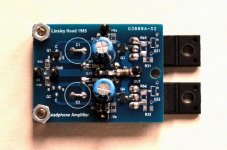
Note that the Public Version of the PCB is different from my own.
It is simplified, a bitmore spread out, and accomdates the original JLH auto-bias circuit.
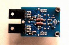
In the end the one single cause of the instability is the long legs of the power transistors.
Morde was using 10mm stand-offs. Reducing them to 5mm, and the amp was stable.
And that took 8 hours !!!!!!
But unluckily I also tried all these other things to try to improve stability.
So now I know what has which effect, etc. Also educational for me.
The BoM will be updated later after Morde has finished the second proto successfully.
Too late now, so photos tomorrow.
😉
Patrick
I was actually working on another phono preamp, but I was curious what was happening.
So it was oscillating, quite badly actually.
After trying a hundred different things all afternoon, including some micro-surgery on the PCB, I was actually at a lost.
But I happened to have my working example on the bench, so I made a visual comparison.
Note that the Public Version of the PCB is different from my own.
It is simplified, a bitmore spread out, and accomdates the original JLH auto-bias circuit.
In the end the one single cause of the instability is the long legs of the power transistors.
Morde was using 10mm stand-offs. Reducing them to 5mm, and the amp was stable.
And that took 8 hours !!!!!!
But unluckily I also tried all these other things to try to improve stability.
So now I know what has which effect, etc. Also educational for me.
The BoM will be updated later after Morde has finished the second proto successfully.
Too late now, so photos tomorrow.
😉
Patrick

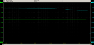
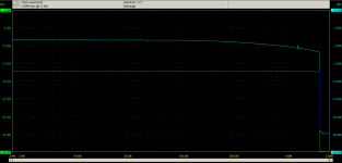
As promised, including frequency responses with or without load.
You can see when when not loaded the amp has a slight (1.5dB) overshoot at ~ 2MHz.
But it is now kept stable by the Zobel network.
At 30R load, it is stable on its own.
Patrick
.
You can see when when not loaded the amp has a slight (1.5dB) overshoot at ~ 2MHz.
But it is now kept stable by the Zobel network.
At 30R load, it is stable on its own.
Patrick
.
Attachments
- Home
- Amplifiers
- Headphone Systems
- The REAL John Linsley Hood Headphone Amplifier