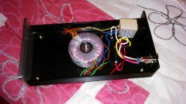
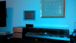
Those are the photos.
Very nice! The chassis has taken more than 9 months to get to you??? That's crazy!
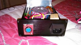
That's right, missing the PSU chassis. It is equal to the phono stage, but still has not arrived.
I'll have to buy another one like, so as not to affect the aesthetics and the remaining two equal boxes.
I ask RJM (since I asked the question but I want to make sure well, since in pre earlier has given me ground loops), the umbilical cord between the case of PSU and case Phono Stage, must be shielded mesh to ground? .
Thank you
Andrew OK. I do understand. I have done so in other preamps, but there has been ground loop.
I had to disconnect the mesh in one end or disconnecting the grounding of the mains 230v.
That is my difficulty. If you could serve me a diagram with connections between the boxes mesh with respect to ground and mains.
I had to disconnect the mesh in one end or disconnecting the grounding of the mains 230v.
That is my difficulty. If you could serve me a diagram with connections between the boxes mesh with respect to ground and mains.
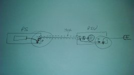
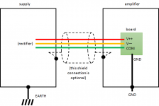
What Andrew said, essentially, see diagram below.
I use un-shielded cable, just 3-wire 16 AWG power cord to carry V++ V-- and COM. This is the DC power supply, it's already fairly noisy and unless RFI is a real problem there is no real need to use a shield ... though you can if you want of course.
If you do you a shield you will need a 4 pin XLR connector or similar, rather than 3 pin normally used here.
Attachments
Last edited:
What Andrew said, essentially, see diagram below.
I use un-shielded cable, just 3-wire 16 AWG power cord to carry V++ V-- and COM. This is the DC power supply, it's already fairly noisy and unless RFI is a real problem there is no real need to use a shield ... though you can if you want of course.
If you do you a shield you will need a 4 pin XLR connector or similar, rather than 3 pin normally used here.
RJM shows it well.
The coloured signal lines are NOT connected to Chassis.
The shield/screen is an extension of the Chassis.
In another Thread they can't get their heads around this fundamental difference.
They are connecting the Signal line to Chassis and then examining why they get interference on the signal line.
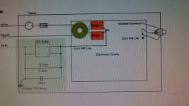
Ok, I understand perfectly. I've seen this circuit placed roper possible ground loop between ground and the input ground.
Sorry but the document does not rise. For if a diode bridge with a capacitor and resistor between the mass and the mass circioto input 230 v. Cheers
Sorry but the document does not rise. For if a diode bridge with a capacitor and resistor between the mass and the mass circioto input 230 v. Cheers
Last edited:
WntrMute2, how are you ?. Just this afternoon I delivered the mail capacitors.
I am really very happy and grateful to you. Just remove the capacitors that come with the kit and install the ones you sent me.
It lies ahead wiring and start it.
Those who know say that we must allow time for the capacitors to be "burned".
I will do so.
Again I am grateful to you for giving me these capacitors.
No such reward their generosity. Greetings and you can count me be helpful. greetings Jose
Thank you very much to all.
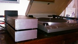
Today October 30, 2015, 00:11 Uruguay time, I finished my long awaited VSPS 300.
I followed the instructions and advice of RJM forum friends.
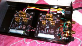
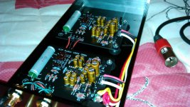
Stressed the great construction of PCB; The quality and accuracy of the kit components.
I have endeavored to buy boxes commensurate with the project and building the best I could get (to have done welding alloy of tin and silver).
All of course can be improved, but this project has been on par, if not better than can be achieved fairly.
Tomorrow is to start enjoying the good sound that gives a vinyl.
But from now without "burning" capacitors and components, I can say that phono preamps I've heard (mine and friends), this is already over.
I thank the friends of the forum; to RJM for your patience; and especially a friend of this forum that has surprised me with their generosity. His nickname is WntrMute2 forum and I have to say it publicly, has taken the trouble to send US to Uruguay by taking over the costs of 4 2.2uF capacitors K73-16 Pio.
I thank you again, and will comment in the future as it has been improving the "VSPS 300".
Joseph.
Today October 30, 2015, 00:11 Uruguay time, I finished my long awaited VSPS 300.
I followed the instructions and advice of RJM forum friends.
Stressed the great construction of PCB; The quality and accuracy of the kit components.
I have endeavored to buy boxes commensurate with the project and building the best I could get (to have done welding alloy of tin and silver).
All of course can be improved, but this project has been on par, if not better than can be achieved fairly.
Tomorrow is to start enjoying the good sound that gives a vinyl.
But from now without "burning" capacitors and components, I can say that phono preamps I've heard (mine and friends), this is already over.
I thank the friends of the forum; to RJM for your patience; and especially a friend of this forum that has surprised me with their generosity. His nickname is WntrMute2 forum and I have to say it publicly, has taken the trouble to send US to Uruguay by taking over the costs of 4 2.2uF capacitors K73-16 Pio.
I thank you again, and will comment in the future as it has been improving the "VSPS 300".
Joseph.
Attachments

- Home
- Source & Line
- Analogue Source
- The Phonoclone and VSPS PCB Help Desk