kilowattski said:Neither one of them looks like they would qualify for the "Worlds Strongest Man Competition". I guess they are going to have rent a fork lift to move the amp around.😀
I don't know. That stack of amplifiers is 5 feet high. 😉
Nelson Pass said:
I don't know. That stack of amplifiers is 5 feet high. 😉
Why are you calling Casey "that Stack of Amplifiers" . 😉
They should be more concerned about that huge Pass Monster amp sneaking up on them from behind the curtains- Muhahaha indeed!
Pass Monster.
Hi all, I have been reading this thread with much amusement. Does anybody remember the Moscode 10,000? " requires direct connection to your power company" was the quote I remember. Sounds like you are trying to outdo that one.
I have been looking at a smps transformer for a big servo supply. The unit is premade with choices of secondary voltages. Continuous throughput is rated at 20,000 watts! The thing is about 8 x 6 x 5 inches. I wonder if that would work for the power supply in your monster? Regards, Steve.
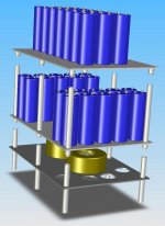
Well, the labs of Smarmy cool have been hard at work! Casey has been experimenting with a 3D modeling program called solidworks. www.solidworks.com
He has started building the amps within the program and we can see exatly how each piece will fit. this is affording us the opportunity now to find out what fittment problems would will run into. it has also allowed us to make some changes we handnt thought of. sometimes a visual is the best muse!!
Attached is a Picture taken from within the program to show some of the components and how there going together.
In the picture you can see the insides of the 3 chassis and how they will stack up. the lower chassis will house the 2x 2KVA transformers and ac related components. the middle chassis will house 20 of the 40 capacitors used and the 2 very large inductors. and the top chassis will house another 20 capacitors as well as the actuall amp stage not yet shown. there will be copper buss bars running right up through the middle of the chassis. and we have even come up with a few proprietry special tricks we are not yet divuldging!
Stay tuned, more to come.
ZC
Attachments
Zero cool's project.
Hi, does that transformer say "PPG Medical Systems" on it somewhere? I have a stack of those in my warehouse. Some are rated at 2kva and some are rated at 3.5kva. The big ones weigh 45 pounds. On the smalller ones, I used a sharp probe to pierce the insulation on the windings, probed and found the exact middle of the secondary. I then tapped into it and made my center tap. This allowed me to get full power out of the thing.
Re: John Bedini, I believe the eleventh transistor was used as a bias temperature compensation. I used to work on them (Bedini) and I will look through my archives. I think I have a reverse engineered schematic I made years ago. 😉
Mr. Bedini used to cut the top off of the output transistors and fill them with epoxy of some sort. I am not sure if there was any sonic value to this. I would assume it would reduce the thermal "singing" of the to-3 cases. If you put a big amp on a load resistor and crank the output, you can hear the devices "sing". My understanding of this; it is caused by the quick heating and cooling of the connection leads inside the device due to the current flow. Also the reason for secondary breakdown.
I will let you know on the schematic. Regards, Steve
Monster amp?
I found this on Ebay, with an isolation transformer and rectification of the 220v mains this would be hard to beat: Copley Controls 265P High Power Amplifier. This thing is rated at +/- 312 amps with over 300 volts output d.c. to 5 Khz! Rated peak power of 44KW! My next subwoofer amp. What do you think guys?
I found this on Ebay, with an isolation transformer and rectification of the 220v mains this would be hard to beat: Copley Controls 265P High Power Amplifier. This thing is rated at +/- 312 amps with over 300 volts output d.c. to 5 Khz! Rated peak power of 44KW! My next subwoofer amp. What do you think guys?
http://cgi.ebay.com/ws/eBayISAPI.dll?ViewItem&category=1498&item=5746211054
Hehehe… Finally, a worthy competitor (if you ignore their noise floor). 😀
Hey, it can also be switched to provide a current output instead of voltage. We can rely on Mr. Pass for the First Watt and this puppy for the remaining 49,999 watts!
-Casey
Hehehe… Finally, a worthy competitor (if you ignore their noise floor). 😀
Hey, it can also be switched to provide a current output instead of voltage. We can rely on Mr. Pass for the First Watt and this puppy for the remaining 49,999 watts!
-Casey
Monster subwoofer amp.
I was thinking..... If you used the Copley and put the subs in the bathroom..... Hey, Beethovan's Fifth helped my movement!!!!
On to the real subject: What about using industrial mosfets or IGBTs. I have some rated 600 volts and 75 amps. That would give a decent soa. As long as you are building a monster, what about using "hockey Puck" transistors along with the matching heatsink? Some of these are rated 600 volts 1200 amps! It would certainly look impressive. I do not know of the sonic quality of such devices. I may build an amp with a pair just to listen to and make a decision. They would be great for the low impedance crowd. Regards, Steve
Heararchy of components. (intentional)
Mr. Pass, I have some industrial mosfets also. They are 600 volt and 75 amp rated. I do not remember the name of the company,... saw one on Ebay,... they sell an amplifier that uses these for output devices. Only one pair per channel.
What other Jfets are available? I thought Hitachi stopped production on the 2sj/2sk series. Please correct me if I am wrong. Are there second sources now?
I have a circuit I developed using Toshiba 250 volt complimentary mosfets. I was able to coax 900 watts into 4 ohms and 1800 into 2 ohms from it. That was with a solid power supply. I like the sound quality of the amp and am working on a switched rail supply with appropriate bias change to use for "normal" listening. No sense cooking the thing with 95 volt rails when the demand is for 10 volts peak. Best regards, Steve
Are those transformers the Powertronix ones they were selling on Ebay awhile ago for $10 apiece?
Re: Heararchy of components. (intentional)
Don't have the answers to most of these questions. The Mosfets
I've seen with ratings those high are packages consisting of
parallel chips. This is about the same thing as you would expect
from one huge chip, as the effects seem to be a functions of
voltage doping and surface area.
Big JFETs? I wish. SITs? Don't think so, but don't really know.
Single output pair? Maybe Gamut, suspect not.
Powertronix? Haven't any info.
gearheaddruid said:Mr. Pass, I have some industrial mosfets also. They are 600 volt and 75 amp rated. I do not remember the name of the company,... saw one on Ebay,... they sell an amplifier that uses these for output devices. Only one pair per channel.
Don't have the answers to most of these questions. The Mosfets
I've seen with ratings those high are packages consisting of
parallel chips. This is about the same thing as you would expect
from one huge chip, as the effects seem to be a functions of
voltage doping and surface area.
Big JFETs? I wish. SITs? Don't think so, but don't really know.
Single output pair? Maybe Gamut, suspect not.
Powertronix? Haven't any info.
What other Jfets are available? I thought Hitachi stopped production on the 2sj/2sk series. Please correct me if I am wrong. Are there second sources now?
There is a local source for these devices in Toronto, I built two Class A/B Amps using 8 per channel for 300Watts output into 8R load.
I am not sure where the dealer is getting them from but they were $24 CAD a matched pair last I checked.
Regards
Anthony
This etailer has been promoting these for a few weeks now.
http://cgi.ebay.ca/ws/eBayISAPI.dll?ViewItem&item=5742802834&ssPageName=ADME:B:FSEL:CA:1
Regards
Anthony
http://cgi.ebay.ca/ws/eBayISAPI.dll?ViewItem&item=5742802834&ssPageName=ADME:B:FSEL:CA:1
Regards
Anthony
Hitachi just merged with Mitsubishi not too long ago- the resulting chimera is now called Renesas. As far as I know, Renesas is still manufacturing lateral MOSFETs, though they dumped TO-3 packages a long time ago in favor of plastics.
The big problem will be finding a distributor. Iv'e gotten some p-channel devices from Electronic Goldmine, and Match-a-Knob appears to stock both flavors. Whether they are real or counterfeit is another question. One way to tell would be to bias a suspect device up at 200ma with the drain and gate nailed togehter, no heatsink. If the Vgs drifts up, its probably a lateral device. If it drifts down, it's most likely a re-marked vertical MOSFET. This of course assumes that it's a MOSFET to begin with. I wouldn't put it past some counterfeiters to remark a cheap bipolar device as a MOSFET...
The big problem will be finding a distributor. Iv'e gotten some p-channel devices from Electronic Goldmine, and Match-a-Knob appears to stock both flavors. Whether they are real or counterfeit is another question. One way to tell would be to bias a suspect device up at 200ma with the drain and gate nailed togehter, no heatsink. If the Vgs drifts up, its probably a lateral device. If it drifts down, it's most likely a re-marked vertical MOSFET. This of course assumes that it's a MOSFET to begin with. I wouldn't put it past some counterfeiters to remark a cheap bipolar device as a MOSFET...
Nelson Pass said:In the hierarchy of audiophile devices:
1 Tubes
2 JFETs
3 Mosfets
4 Bipolar
5 Diodes
6 IGBTs
😎
Yikes, Pass will go tubes sooner or later !
Or, he is a diplomat with a strong dislike to IGBT's.
I prefer the latter

But what do i know, i am still reading a book about Speed and its taking me ages.
The only speed in Holland comes in a plastic bag !
OK, the list was what we would call tongue-in-cheek. IGBT's
are more linear than diodes. 🙂
And don't worry, I have no intention of designing with tubes,
although I do like to listen to them.
😎
are more linear than diodes. 🙂
And don't worry, I have no intention of designing with tubes,
although I do like to listen to them.
😎
And don't worry, I have no intention of designing with tubes,
Is that because tube circuits are harder to design that Solid State Mr. Pass?
Regards
Anthony
What good is a silver ladel, if you can't use it to stir things?
- Status
- Not open for further replies.
- Home
- Amplifiers
- Pass Labs
- The Pass Monster?