Dan,
That may end up being an option. Im going to remove the cone correction plate and run my other driver and see how that goes first. I will be paying more attention to things like excursion levels this time.
That may end up being an option. Im going to remove the cone correction plate and run my other driver and see how that goes first. I will be paying more attention to things like excursion levels this time.
Hi Josh,
Your model shows a difference with your measurements because this type of folding repositions the S2 of the system out of the centre of the driver. In many of these cases only cone volume correction doesn't help enough for repositioning the S2 point (To correct your model you could enlarge the distance between S1-S2 and take the same amount off from S2-S3. You can also raise the Le value in your model since the inductance raises as frequency drops).
In my view what happens is that the pressure in the first half of the cone (closest to the beginning of the horn) is lowest and the pressure in the second half of the cone (near the correct S2) is the highest. In other words, the first half of the cone no longer has enough pressure (spring effect) to keep the cone under control. This effect together with relative high Fs of the 21SW115 (32Hz, which is very close to the excursion peak of the system in my view), can drive the cone into self resonance. This can end in damaging the cone over periods of time at high excursion.
Last edited:
djim:
Not sure I understand? I always assumed pressure on cone closest to S1 was highest and is why cone failures seem to concentrate there, not lowest.
To that end, I've employed a circular compression "plate" to help evenly distribute the pressure on the cone -- or a smaller S2 / much larger S1 "cone correction" to provide additional 'air spring' on the S1 side of the cone.
am I doing it backwards?
Hmmm...I had thought that the pressure would be highest near the start of the line where it is tighter as well.
Why would the S2 be shifted that much from cone center when the angled panel ends almost exactly mid cone which is how it is modeled? If anything there should probably an additional horn section accounting for the different expansion under the second half of the cone. The cone volume is what is not accounted for well. There is a fudged vtc and atc value in the simulations but I'm not sure how accurate that is. There is some difference caused by the multitude of bends present as well I'm sure. Still the response and impedance looks pretty darn close all things considered.
I may have a chance to do some tests with my other driver and the cone correction plate removed this Saturday morning. I'm considering this as accelerated reliability and limit testing. If the driver survives the full test signal regimen it should be very unlikely to be damaged with even heavy program use. If it does not, it may be time to hack out the throat panel to drop the compression ratio and equalize the forces on the cone somewhat. I hope it doesn't get to that point.
josh:
what's the odds that you can band-aid sufficiently your torn cone for this test, and not risk another?
btw, here's a pic of what I mean about an enlarged S1 to increase the "air spring"
what's the odds that you can band-aid sufficiently your torn cone for this test, and not risk another?
btw, here's a pic of what I mean about an enlarged S1 to increase the "air spring"
Attachments
Last edited:
Hi Josh and Jim,
I'll try to explain.
The pressure supposes to be optimal at S2. In our ideal models we position S2 at the centre of the driver. In these models S1 is part of the horn, more exactly the beginning of the horn and represents the high pressure zone. The left picture represents such model.
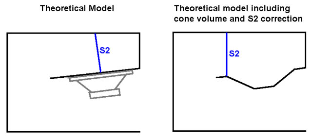
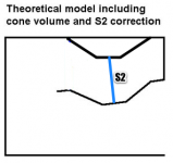
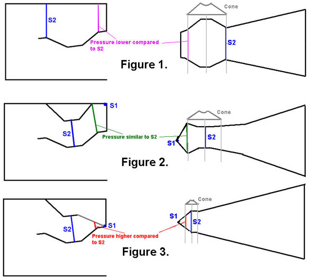
However, in reality we add extra volume around the S2 area that is introduced by the volume in the cone. This cone volume interrupts the ideal expansion rate of our theoretical models. The right picture represents such model. Because of the extra cone volume, this area starts to work as an independent compression chamber. Therefore S2 shifts towards one edge of the driver (or beyond) as you can see in the right picture. Also S1 no longer is part of the horn but part of the compression chamber. Because it doesn’t represent the beginning of the horn any longer, the pressure at S1 starts to drop in relation to the pressure around S2. S2 now represents the beginning of the horn.
Josh, I am afraid the narrowing panel from S2 to S1 in the Othorn is not part of the horn but part of the compression chamber. Therefore it will make the pressure differences between the two edges even worse.
By using a "compression plate" like Jim described, you introduce a compression chamber between the driver and the horn. In such case S1 is still part of the horn and represents the beginning of the horn (high pressure).
I'll try to explain.
The pressure supposes to be optimal at S2. In our ideal models we position S2 at the centre of the driver. In these models S1 is part of the horn, more exactly the beginning of the horn and represents the high pressure zone. The left picture represents such model.
However, in reality we add extra volume around the S2 area that is introduced by the volume in the cone. This cone volume interrupts the ideal expansion rate of our theoretical models. The right picture represents such model. Because of the extra cone volume, this area starts to work as an independent compression chamber. Therefore S2 shifts towards one edge of the driver (or beyond) as you can see in the right picture. Also S1 no longer is part of the horn but part of the compression chamber. Because it doesn’t represent the beginning of the horn any longer, the pressure at S1 starts to drop in relation to the pressure around S2. S2 now represents the beginning of the horn.
Josh, I am afraid the narrowing panel from S2 to S1 in the Othorn is not part of the horn but part of the compression chamber. Therefore it will make the pressure differences between the two edges even worse.
By using a "compression plate" like Jim described, you introduce a compression chamber between the driver and the horn. In such case S1 is still part of the horn and represents the beginning of the horn (high pressure).
Last edited:
That is including (a not working foamy) cone volume correction and repositioning of the S2... 😀🙄
- Take bad cone
- fill with spray foam
- glue in place...


Edit: to show the difference...(and make it complicated):
Last edited:
josh:
what's the odds that you can band-aid sufficiently your torn cone for this test, and not risk another?
I'm one step ahead of you. I'm trying some rubberized epoxy applied on both sides of the cone in the compromised areas. I will then mount the driver rotated so that the good section of cone is in the area that was caused damage last time. Might work. But I doubt it will hold up to >150 volts 😀
If further testing indicates that additional modification is in order I will probably cut out the angled throat panel. I won't be able to cut in and put the angled piece that you show in the corner of the bend. Things are very tight in there and I won't be able to work that cleanly.
🙄
- Take bad cone
- fill with spray foam
- glue in place...
Not a bad idea, although I believe that adding further material into the throat area on this horn is not going to help the situation with the compression ratio so high to begin with. What product in particular did you have in mind? Expanding foam used in packaging?
Last edited:
#1 priority for me would be to yolk out the L12 wedge...
If you want tough TOUGH foam grab some Gorilla glue.
I'd try 20/1 Glue/activator, pre-mix throughly in a solo cup 6oz glue and two teaspoons of water.
Pour into cone and rotate to coat.
Set in sun and avoid disturbing.
Great stuff should also be good enough, and although I've not used it the Pond formula, I think it's for setting stone, so that would be the one I'd try. With spray foam it is important to go one reasonable layer at a time so it can cure fully before the next layer, else later on it will expand and you then you'd be proper fak'd.
Hi,
All these examples use a maximum size hole for the driver. Jbell (Post #143) is indicating that he uses a compression plate, Post #143 (just like screamersusa here: http://www.diyaudio.com/forums/subwoofers/131852-live-sound-specific-tapped-horn-thread.html). This plate should vent into the horn with an opening reflecting S2. The shape and position of the opening can then be optimized to properly couple the driver through the compression chamber to the horn. The driver should be mounted with a spacer plate that is thick enough to prevent the cone from touching the compression plate. Additionally, jbell's suggestion from Post #145 might help.
Regards,
My "redneck" explanation of a compression chamber in a TH is that it gives a bit of driver resistance below Fc, to keep the driver from unloading as quickly. It also prevents uneven cone loading from side to side, as any pressure differences at the compression plate opening are more centered over the driver.
My experience is that I have not driven a TH with a compression plate into cone failure, where without it, I have. Yea, not very scientific I know...
I'm still experimenting with overly large S1 vs S2... to see what kind of failures I can reproduce.
is that the info you are looking for?
My experience is that I have not driven a TH with a compression plate into cone failure, where without it, I have. Yea, not very scientific I know...
I'm still experimenting with overly large S1 vs S2... to see what kind of failures I can reproduce.
is that the info you are looking for?
If the driver gets killed by too much pressure, how can you save it by adding more pressure from the compression chamber? In other words, that sounds like a contradiction to me... or... the driver didn't get killed by too much.........😉
What use does it have to suppress excursion below the first excursion dip besides loosing power ? In other words, using your low cut filter at the excursion dip gives the same results but without the power loss. By using it in combination with a dynamic EQ you can even filter from a certain dB level and leave the low end untouched below that level.
What use does it have to suppress excursion below the first excursion dip besides loosing power ? In other words, using your low cut filter at the excursion dip gives the same results but without the power loss. By using it in combination with a dynamic EQ you can even filter from a certain dB level and leave the low end untouched below that level.
If the driver gets killed by too much pressure, how can you save it by adding more pressure from the compression chamber? In other words, that sounds like a contradiction to me... or... the driver didn't get killed by too much.........😉 .
Agreed...The particular case here indicates that there was obviously too much of something already whether that be excursion, physical cone contact with the cone correction plate, pressure, or perhaps highly uneven loading on the cone surface.
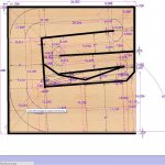
That is including (a not working foamy) cone volume correction and repositioning of the S2... 😀
Edit: to show the difference...(and make it complicated):
Fig #3 is similar to what the configuration was during testing.
Actual representation shown below with marking of where the cone damage occured...As you can see the added material eats up a lot of volume in the throat area and there is likely an extreme amount of force developed with the power inputs used. I expect at least somewhat lowered forces on the cone with its removal.
The plate was nothing more than the scrap cutout from an 18",15" and 12" driver glued together.

BTW Dan I am assuming you mean to use the cone as a mold to develop a near ideal cone correction form? This is what I took your meaning as. Do you mean something different?
Last edited:
If the driver gets killed by too much pressure, how can you save it by adding more pressure from the compression chamber? In other words, that sounds like a contradiction to me... or... the driver didn't get killed by too much.........😉
What use does it have to suppress excursion below the first excursion dip besides loosing power ? In other words, using your low cut filter at the excursion dip gives the same results but without the power loss. By using it in combination with a dynamic EQ you can even filter from a certain dB level and leave the low end untouched below that level.
1. I don't think the driver gets killed by too much pressure, but by uneven pressure. The compression plate evens things out.
2. people are stupid.... I have never personally killed a driver behind the controls at an event... I'm not always behind the controls....
3. The only sure way to keep stupid people from killing subs is self powered cabinets with on board dsp, highpass, limiter, etc....
The DIY roahcell carbon expoy reinforced monocoque composite matrix™😀 was what I thought you would end up with, I had not assumed you would get lucky with the mold release.BTW Dan I am assuming you mean to use the cone as a mold to develop a near ideal cone correction form? This is what I took your meaning as. Do you mean something different?
If you want to make a mold don't forget to include the baffle cutout.
Though a shame to entomb in the cab as I hear the 21" DIY roahcell carbon expoy reinforced monocoque composite matrix sugegasa™ is a popular item this summer season.

If you are careful when removing the spider it can be reused as the ultimate suspension to float the hat on your noggin 😀
Shoot...a liberal application of Crisco and it aught to pop right out of there. There's also a couple of cans of Flex seal coating overtop of the rohacell in a can
Last edited:

- Home
- Loudspeakers
- Subwoofers
- The Othorn tapped horn