I've got quite a few smaller ones but annoyingly only up to T6. Amusing that the only troublesome part of the build was actually getting the screws in 😀
Or buy a torx bits set and find out yourself, they always come in handy some day! [emoji2]
I have just finished building another O2, it worked fine, everything measured right but the regulator (both U5 and U6) get really hot, i can only touch the metal tab for 1s, i'm using a 15VAC adapter. The "hot" is very subjective so i measure the idle current draw and got 60ma with the amp on, no music playing and then remove all the opamp except the NJM2903 and got 40ma, that's really strange. I think it must be shorted some where but double check all the solder, they look all fine. Does any one have an idea?
1/ With the power switch on the PCB set to off, do the regs get hot ?
2/ What is the DC voltage on the input of each reg ?
3/ What is the DC output from each reg ?
Where in the circuit are you measuring the current draw ?
2/ What is the DC voltage on the input of each reg ?
3/ What is the DC output from each reg ?
Where in the circuit are you measuring the current draw ?
1/ With the power switch on the PCB set to off, do the regs get hot ?
2/ What is the DC voltage on the input of each reg ?
3/ What is the DC output from each reg ?
Where in the circuit are you measuring the current draw ?
1/ No, the reg don't get got.
2/ About +-22V, perfectly normal.
3/ About +-11.7V.
I solder 2 temporary 9v battery socket then disconnect one wire and use a DMM set to current measurement "heal" that gap between the wire and pcb pad and get the number.
Your voltages sound fine. I'm a bit unsure on the way you are measuring the current though. Have you got batteries fitted ? If so then they will draw current to charge and add to the overall result. 60ma from either rail gives a dissipation of around 0.7 to 0.75 watt per reg and so is within acceptable limits although it will feel hot.
The easiest way to measure the current draw of the amp itself is to remove the batteries and switch it on and then place the meter set to a 'medium' current range across D1 and then D5. The resistance of the meter will just short out the diode and give a pretty accurate result... nothing to unsolder or disconnect.
The easiest way to measure the current draw of the amp itself is to remove the batteries and switch it on and then place the meter set to a 'medium' current range across D1 and then D5. The resistance of the meter will just short out the diode and give a pretty accurate result... nothing to unsolder or disconnect.
Hello, I have just completed the assembly of my o2 amplifier.
After checking everything, i tried powering it on with test headphones. When i did, it just output a loud static noise. I havn't been able to find other people with this issue. so I'm a bit at a loss. I noticed the U6 mosfet get a lot warmer than the U5 mosfet. So I'm thinking that one is the problem. Has anyone here encountered this problem before, and maybe found a fix?
After checking everything, i tried powering it on with test headphones. When i did, it just output a loud static noise. I havn't been able to find other people with this issue. so I'm a bit at a loss. I noticed the U6 mosfet get a lot warmer than the U5 mosfet. So I'm thinking that one is the problem. Has anyone here encountered this problem before, and maybe found a fix?
Hi Karl and welcome to diyAudio.
U5 and U6 are linear voltage regulators... in the first instance I would suggest you follow the guide I put together here at post #3775,
http://www.diyaudio.com/forums/head...o2-headphone-amp-diy-project.html#post3806667
U5 and U6 are linear voltage regulators... in the first instance I would suggest you follow the guide I put together here at post #3775,
http://www.diyaudio.com/forums/head...o2-headphone-amp-diy-project.html#post3806667
Thanks for the reply. I had some time now so i tried it.
I have an issue at the first step already. When i set my multimeter to DC Volts and measure at the places you mentioned i get 0.449[V].
I checked all the diode polarity, and no faults there. I checked the 7812 and 7912 mosfets and they are also correctly places with no bridges.
When i go to step 2 and measure the non striped end of d3 i get 0.1 milli volts.
Linear voltage regulars* sorry. First time working with them and i just think mosfet everytime i look at them 🙂
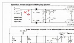
This sounds as though something is amiss with either the AC adapter or its connections to the board.
Can you measure AC voltage between these two points. You should see between 12 and 20 volts AC. Make sure you have it on AC for this one measurement.
Also are you sure your meter is OK. Check it by reading the voltage of a battery. Your meter should then be set to DC for this.
Can you measure AC voltage between these two points. You should see between 12 and 20 volts AC. Make sure you have it on AC for this one measurement.
Also are you sure your meter is OK. Check it by reading the voltage of a battery. Your meter should then be set to DC for this.
Attachments
I tried measuring a battery and the meter works fine.
Just to make sure I'm reading the diagram correctly, you want me to turn the power on and measure between these two points?

Just to make sure I'm reading the diagram correctly, you want me to turn the power on and measure between these two points?
I can't tell from the picture simply because I've never actually seen an O2 board... we work from the circuit 🙂
You are measuring between the striped end of D4 and the main ground on the board which is the junction of all those four capacitors in the diagram I posted above.
Meter on AC volts and you should see between 12 and 20 volts AC.
You are measuring between the striped end of D4 and the main ground on the board which is the junction of all those four capacitors in the diagram I posted above.
Meter on AC volts and you should see between 12 and 20 volts AC.
Wow that impressive.
I get 16.5[V]
For some reason the LED stays on and slowly fades after turn off the power, after i took out U1-U4.
I get 16.5[V]
For some reason the LED stays on and slowly fades after turn off the power, after i took out U1-U4.
That looks OK. The LED fading out is normal and due to the large capacitors holding charge.
So next step is to check the DC voltage (so meter now on DC volts) coming out of the regulators U5 and U6. You should see plus 12 volts from U5 and minus 12 from U6. Keep the meters black lead on ground for all these measurements. Be careful not to short anything out with the meter probes. You can pick these voltage up on D1 and D5.
So next step is to check the DC voltage (so meter now on DC volts) coming out of the regulators U5 and U6. You should see plus 12 volts from U5 and minus 12 from U6. Keep the meters black lead on ground for all these measurements. Be careful not to short anything out with the meter probes. You can pick these voltage up on D1 and D5.
Perfect.
Now I'm assuming U1, 2, 3 and 4 are still removed. The next quick check is to confirm that the voltages you have just measured are present on the socket of U2. You should have plus 12v on pin 8 and minus 12v on pin 4.
If that is OK then switch OFF and fit just U2, the NJM2903. Make sure you get it the correct way round.
You should now see the plus 12 volts on pin 8 of the remaining empty sockets and the minus 12v on pin 4 of the sockets.
I checked and confirmed the 12[V] on pin 8 and -12[V] on pin 4.
I've now inserted the U2 back into the socket while it was off, but I'm a little unsure of your explanation of what the values of the remaining pins should be now, with the power on.
EDIT: Oh on the other empty sockets, nevermind I'll test it out
I've now inserted the U2 back into the socket while it was off, but I'm a little unsure of your explanation of what the values of the remaining pins should be now, with the power on.
EDIT: Oh on the other empty sockets, nevermind I'll test it out
Last edited:
- Home
- Amplifiers
- Headphone Systems
- The Objective2 (O2) Headphone Amp DIY Project