The LED is open circuit as you have nearly 20 volts across it. I was just wondering if we could fiddle it somehow as a test. Shorting the LED out won't work.
If you have a resistor somewhere in the region of 1k5 to say 3k3 then you could fit that in place of the LED as a test. The rails should then come up.
If you have a resistor somewhere in the region of 1k5 to say 3k3 then you could fit that in place of the LED as a test. The rails should then come up.
If you haven't a resistor then you can still test the FET's and the rest of the amp.
1/ Remove U2
2/ Connect a link between pin 1 and pin 4 of the empty socket.
The amp should function normally with the plus and minus 11.7 volts appearing on pins 8 and 4 of all the remaining opamps.
Although the LED is marked as mission critical and not to be substituted you can in fact use pretty much any high efficiency LED of the same colour (LED volt drop is colour dependent). The exact cut off point of the comparator can be trimmed if needed by altering R9 or R5 to get it to work at any desired voltage.
When I first checked resistance across the LED out of circuit, it was ~1500 K. Now it's ~2000 K (limit of my DMM).
I installed a 1.5 K 1/8 watt gain resistor that actually measures 1440 (in D7).
With power on, plugged in, and U2 installed, voltages at D3 and D4 were very wrong. Voltage from BT1+ to BT2- was also very wrong. U6 got very hot. U5 was not hot at all. So, maybe the resistor was too low and was drawing to much current?
Should I reinstall the LED and do the second test with removing U2 and shorting pin 1 and pin 4 of the empty U2 socket? Or leave the resistor?
I think I'm going to purchase new a new LED, U2, Q1, Q2, U5, and U6. That should cover anything that is wrong at a relatively low cost.
The red LED in the BOM has a minimum order of 5000. So, I found this one which is green with the same forward voltage and current. The luminous intensity is 16 mcd rather than 2 mcd, though. I think this is OK.
The red LED in the BOM has a minimum order of 5000. So, I found this one which is green with the same forward voltage and current. The luminous intensity is 16 mcd rather than 2 mcd, though. I think this is OK.
You sound to have other issues going on here......
Replacing the LED with 1500 ohm (1k5) could only draw in the worst case around 16 milliamps. Worst case assumes U2 is zapped and has the +12 volt rail appearing at pins 3 and pins 5. That would place the full 24 volts across the 1k5 but nothing bad would happen as the current is so low.
So that is definitely not the issue as to it causing things to get hot and the rails to collapse.
If U2 is OK then swapping the LED for a 1k5 should have enabled the FET's to turn on and pass the rails through to the rest of the circuitry.
If you have a short or a problem on the output side of the FET's then this could then cause U6 to get hot. That's the most likely thing that has happened.
Look at the circuit.
If you link the FET's out by shorting Drain to Source for each, and also remove U2 then you have completely bypassed all that section of circuitry. Assuming no problems in the rest of the unit then it will work and you should have your -/+ rails present at all points. If it doesn't then you have additional build problems in the rest of the unit.
Quick checks to see where its all at.
1/ Remove the 1k5 (leave the LED out but have U2 fitted) and confirm you are back to having -/+ 11.7 volts on pins 4 and 8 of U2. If the voltage is not correct then that has to be fixed before continuing.
2/ Switch off and check for shorts between pins 4 of the remaining opamps and ground.
3/ If you find a short (or a very low resistance reading) then obviously the cause has to be found.
4/ If you can not find a short then now remove the remaining opamps.
5/ Now link the FET's out and switch on.
You should have -/+ 12 volts on pins 4 and 8. If that is not present or the regulators now get hot then there is a hidden fault or short somewhere.
Thank you for all of the help, Mooly. I really appreciate it.
I probably won't have time to test until 2016/11/11 at 2:00 GMT. So, I want to make sure I understand everything before then. I'll post with results as soon as I can.
Is this where you got the worst case value?
If step 1 fails, should I stop there or continue with step 2?
For step 2, do you mean check the resistance from ground to pin 4 of U1, U3, and U4?
For step 4, only U2 is installed. So, that's the only one to remove, right?
For step 5, is there a "correct" way short a FET? I don't have alligator clips, so solder a wire between the pins?
Does the LED I linked look OK to you?
I probably won't have time to test until 2016/11/11 at 2:00 GMT. So, I want to make sure I understand everything before then. I'll post with results as soon as I can.
Is this where you got the worst case value?
Code:
I = V / R = 24 V / 1500 Ohms = .016 A = 16 mAIf step 1 fails, should I stop there or continue with step 2?
For step 2, do you mean check the resistance from ground to pin 4 of U1, U3, and U4?
For step 4, only U2 is installed. So, that's the only one to remove, right?
For step 5, is there a "correct" way short a FET? I don't have alligator clips, so solder a wire between the pins?
Does the LED I linked look OK to you?
Yes, its just ohms law. Worst case current for the resistor would be if the +12 rail appeared on the top of it. The lower end is connected to -12 volts.
If step 1 fails then you can still check for shorts although you would obviously need to fix the problem to get the rails back and to be able to do voltage checks.
Checking for shorts means trying to see if there is a low resistance (or short) across the 'switched' rails. The 'switched' rails are simply the power supplies after the FET's. All the FET's do is to operate as switches turning the amp off by removing power to the opamps. I only mentioned checking pin 4 to ground as you said it was the negative regulator that got hot but lets check both pins 8 and pins 4 to ground for shorts.
Step 4 and Step 5 really go together.
If you've reached this point and not found a short then we remove all the opamps (U2 can be either be left in place or removed, it doesn't matter) and link out the FET's. Linking out the FET's simply applies the -/+12 volts to the whole board and bypasses the operation of the comparator. Just a bit of wire to link the FET's is all that is needed. You are linking the left side to right on each FET to carry the supply across. Make sure you get the correct pinouts on the board.
So to recap...
We are aiming to get the -/+12 volts back on pins 4 and 8 of U2. With the 1k5 removed you should be back in that position.
That's the first thing to aim for.
I suspect that fitting the 1k5 did actually cause the comparator to operate correctly and apply power to the rest of the amp... and that is where the main problem is.
It may be very worthwhile fitting a limiting resistor to the incoming AC (low voltage side, not the mains) to the 02 board. Better to have a resistor get hot and burn than other parts. Something like a 100 ohm 1 watt carbon might do the trick.
Or... use a couple of cheapo zinc carbon batteries for testing. They cant supply much current at the best of time 😉
@ tbp
I used red LED salvaged from old modem (forward voltage 1.74V with 33K resistor). Worked just fine.
I used red LED salvaged from old modem (forward voltage 1.74V with 33K resistor). Worked just fine.
I replaced Q1, Q2, U2, U5, & U6, removed the resistor in D7, double checked/redid a few joints, and confirmed U2 pins 4 and 8 are back to +/- 12 V. U1,3,4 pins 4 & 8 are very low (not ~12 V).
I didn't find any shorts between ground and pins 4 & 8 of U1,2,3,4.
So, there is an issue hiding somewhere. For what it's worth, BT1+ to BT2-, D4, D3, D1, and D5 all look good.
I'll try linking out the FETs now.
I didn't find any shorts between ground and pins 4 & 8 of U1,2,3,4.
So, there is an issue hiding somewhere. For what it's worth, BT1+ to BT2-, D4, D3, D1, and D5 all look good.
I'll try linking out the FETs now.
With the FETs linked out, I'm getting +/- 11.7 V on pins 4 and 8 of U1,2,3,4. So, the FETs aren't working properly. Since the FETs are new, I don't think they are at fault. So, the gate supply must be off. The gates are supplied by pins 1 and 7 of U2. Here are the U2 values:
Pin 1 = 9.1
Pin 2 = -8.9
Pin 3 = 11.1
Pin 4 = -11.7
Pin 5 = 11.2
Pin 6 = 9.2
Pin 7 = -11.7
Pin 8 = 11.7
Q1 Gate = 7.6
Q2 Gate = -11.7
Reading/looking more.
Pin 1 = 9.1
Pin 2 = -8.9
Pin 3 = 11.1
Pin 4 = -11.7
Pin 5 = 11.2
Pin 6 = 9.2
Pin 7 = -11.7
Pin 8 = 11.7
Q1 Gate = 7.6
Q2 Gate = -11.7
Reading/looking more.
Here are the U2 values:
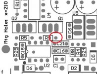
Suggestion: the power management circuitry around U2 is a little different than the audio part of the board in that it is referenced to the negative supply rail, rather than ground. In other words, for all pins of U2 except the power pins (4 & 8) put your negative meter lead on U2 pin 4 (which the is negative rail) rather than ground. Even better - put your negative meter lead on the right leg of R9 circled in the image below. It is connected to U2 pin 4 by PCB traces, so same negative power rail, but less chance of your meter probe slipping off an IC pin and shorting to other pins.
Those new readings vs. the negative rail would likely help Mooly or anyone else. They would make a lot more sense just looking at them. 🙂
Here, you can see why on NwAvGuy's schematic:
https://drive.google.com/file/d/0B52Awjeyc5zKMjRlYjlhNGItNGJlNC00ODlmLWIwM2MtNDI4ZWU4YWRjY2Y4/view
See how one end of R9 and one end of the LED D7 both connect to the negative power rail going to U2 pin 4? U2 is a comparator. Its input pins 2 & 3, connected to the other end of those parts, are comparing the voltage across the LED here to the voltage across R9. R9 and R5 form a voltage divider across the two power supply rails. So really what the comparator is comparing is whether that LED voltage is higher or lower than the divided-down rail to rail power supply voltage, which is how it knows if the batteries (the power rails) are low enough to cause the comparators to change state and toggle the mosfets.
From your ground-referenced measurments I *think* it appears Q2 is going to be off, its gate voltage (U2 pin 7, a comparator output) is same as the Q2 source voltage (the negative rail) with the open collector output transistor in the comparator output pulled down, so less than 2V gate-source and the mosfet is off. But Q1 will probably be "on" since the Q1 gate (pin 1 comparator output) is 3V or so below the 11.7Vdc Q1 source (the positive power rail), which is enough to turn it on (anything more than 2V or so). So this isn't good! Both power rails should either be on at the same time or off at the same time. That is what the two comparator sections do, one goes high when the other goes low (and vise versa) to change the mosfet's state at the same time. You are looking in the right place in the O2 circuitry, U2 controls the mosfets.
If you could post a high resolution photo of the top and bottom of the circuit board around U2 that would help Mooly and anyone else a bunch too. 🙂 Can see if you have a part out of place, wrong part, solder bridge, bad solder connection, etc.
I'm off to bed and just did a drive-by post here, lol. Mooly is wizard with the O2 troublehooting! Good luck. 🙂
Attachments
Last edited:
The voltages show the comparator is in the wrong state. The supplies are good.
The problem is around pins 3 and 5. The voltage here is determined solely by the LED and in practice that means pins 3 and 5 will be just a couple of volts more positive than pin 4 at all times.
Either the LED is open circuit or there is open circuit print around there. Or possible the LED is in backwards.
With your meter BLACK lead on pin 4 you should have 0.000 volts on the cathode of the LED and around plus 1.8 or so on the anode of the LED. The anode also connects to pins 3 and 5.
I got it working! I didn't have the LED in during the tests above. Once I installed the LED, +/- 11.7 appeared at pins 4 and 8 of U1,2,3,4.
The other voltage and resistance measures looked good (including at P2). So, I installed the ODAC and everything seems to be working as intended.
Thank you so much for the help, @Mooly (and others)! I could not have fixed this if not for you.
The other voltage and resistance measures looked good (including at P2). So, I installed the ODAC and everything seems to be working as intended.
Thank you so much for the help, @Mooly (and others)! I could not have fixed this if not for you.

Right Channel Drop from ODAC only
Hey guys,
Finished putting together my DIY O2/ODAC today. I wanted to be able to use it as a standalone line-level DAC, so in addition to the standard setup I wired "line out" on the ODAC to rear panel RCA jacks, and "audio out" was wired under the board and soldered to J2. The solder pads on the bottom of ODAC are filled and the ground traces under J2 have been cut. Everything is arranged per JDS instructions as listed here for "dedicated RCA DAC line output":
http://www.jdslabs.com/pdf/Custom O2-ODAC - Complete Soldering Guide.pdf
When I connect an analog source everything works beautifully. When running USB and RCA out to my stereo everything works beautifully.
I only have a problem when trying to listen to headphones using USB in. In that case the left channel sounds great and the right channel is dead silent. I have triple checked for solder bridges or unintentional grounds. I disconnected the wires and used a DMM to make sure they all conducted properly, then soldered everything back together again. Still no luck.
Any thoughts? Is it possible J2 could be faulty?
you could plug in a cable to line-in(J2), and see if you then get proper sound from USB to your headphones.
If J2 was faulty, so that it shorts out the right channel when nothing is connected, it should then work, since it worked also when you used J2 to connect an analog source.
Edit: no wait, if you connect a source to J2, the ODAC would be shortet out anyway.😛
If J2 was faulty, so that it shorts out the right channel when nothing is connected, it should then work, since it worked also when you used J2 to connect an analog source.
Edit: no wait, if you connect a source to J2, the ODAC would be shortet out anyway.😛
Last edited:
Thanks for your reply MooCow. I'll try your idea anyway just to see what happens and let you know.
I was obsessing over this last night and came to the following conclusions:
1. the ODAC is working right because the RCA outputs work
2. On it's own, the O2 is working properly because it works with an analog input, and that also means that J2 is at least connected to the board properly.
I guess this leaves the solder pads on the bottom of ODAC and the connection between ODAC and J2. I've checked both of those carefully, but what I do not know how to check is whether the shorts in J2 are working like they should.
Also, I followed the JDS example for soldering to the "audio out" pads on ODAC, but can anyone confirm which pad is which? Maybe the right channel is wired to ground?
Thanks all!
Never mind, I figured it out!
One of the pads on the bottom of ODAC wasn't quite soldered in properly. Thanks for the consideration!
One of the pads on the bottom of ODAC wasn't quite soldered in properly. Thanks for the consideration!
Hello my friends, I would like to build a O2 to use with IEMs only.
MooCow suggested me to build this with OPA1688.
I´m newbie in electronics and DIY project, i´m good in follow instructions, but I don´t understand well how the projects works. Then I would like to understand better the diference OPA1688 can make in this amp.
Also I read some reviews of the original project, and some people say the O2 is a good amp, but a bit too analitical, kind of cold sound... lacking of bass punch etc.
Is there any improvement in this project that makes it sound more warm or musical?
Please keep me up with the possibilities to get the best O2 for my IEMs.
Thanks!
I have built several O2's and just recently replaced the 4556's with 1688's..easy to do.
Also you might look at AGDRs Super Cmoy:
http://www.diyaudio.com/forums/head...y-2x-9v-real-ground-headphone-relay-pcbs.html
Also check his agdraudio.com site, he sells this Super Cmoy with 1688.s
Alex
http://agdraudio.com/cmoy.html
Also you might look at AGDRs Super Cmoy:
http://www.diyaudio.com/forums/head...y-2x-9v-real-ground-headphone-relay-pcbs.html
Also check his agdraudio.com site, he sells this Super Cmoy with 1688.s
Alex
http://agdraudio.com/cmoy.html
Last edited:
- Home
- Amplifiers
- Headphone Systems
- The Objective2 (O2) Headphone Amp DIY Project