I took a multistranded cable and ran it from the input ground on the bottom of the board to the back of the enclosure and just like sofaspud removed some of the paint around a screw hole. The cable strands are pinned between the back plate and the chassie.
there is a picture on NwAvGuy's blog for sure showing how the board is grounded to the case. There it is grounded at the front. I would run the ground wire to the back if a clear panel is used in the front, just for the looks 😉 If grounded to the front one of the 1/8W resistor legs will do fine.
I use a Dremel to grind off a bit of the material around the screw hole so the panel sits flush afterwards.
I have to build a couple of amps tonight and will take a pic or two and post them here.
Stefan
I use a Dremel to grind off a bit of the material around the screw hole so the panel sits flush afterwards.
I have to build a couple of amps tonight and will take a pic or two and post them here.
Stefan
there is a picture on NwAvGuy's blog for sure showing how the board is grounded to the case. There it is grounded at the front. I would run the ground wire to the back if a clear panel is used in the front, just for the looks 😉 If grounded to the front one of the 1/8W resistor legs will do fine.
I use a Dremel to grind off a bit of the material around the screw hole so the panel sits flush afterwards.
I have to build a couple of amps tonight and will take a pic or two and post them here.
Stefan
Hello Stefan, when do you get EU powersupplies back in stock?
Hello Stefan, when do you get EU powersupplies back in stock?
My supplier will ship tomorrow, so with a bit of luck they will be back in stock Friday.
Stefan
Hi,
I just finished assembling the O2 amp kit I got from Stefan.
I completed the testing procedure as suggested by NwAvGuy and it is Ok with a tollerance of 0.2 VDC of my cheap DMM.
I connected the amp to an old Ipod headphone and... I got music from the right channel but only silence from the left one.
I also went through the troubleshooting section and again my amp seems OK.
So now I am going to follow the final NwAvGuy's suggestion: ask to DIYaudio!
I had a look to this thread, but there are so many posts and it is hard to find the right answer to my problem. I think you understood that I am not a real expert. I suspect a stupid problem with my input or output jacks. Any suggestion?
Thank you for your help
northernsky
Hi,
problem solved: just one of the pot connection poorly soldered.
I'll wait tomorrow to connect my HD600
northernsky
problem solved: just one of the pot connection poorly soldered.
I'll wait tomorrow to connect my HD600
northernsky
I'll wait tomorrow to connect my HD600
Better wait for day after tomorrow to connect those HD600😉
Chk/ re-flow all the contacts for dry joints.Let the O2 run for couple of hours with music playing with cheapo h/p connected all the time. If using batteries observe the function of PM & look out for power ON/OFF hysteresis cycle & thumps.
Better wait for day after tomorrow to connect those HD600😉
Chk/ re-flow all the contacts for dry joints.Let the O2 run for couple of hours with music playing with cheapo h/p connected all the time. If using batteries observe the function of PM & look out for power ON/OFF hysteresis cycle & thumps.
You are right! I already made a mistake.
Thanks again to this forum: with your help, following my gainclones, I have another box working
northernsky
grounding PCB to case How To...
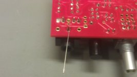
As promised, some pictures taken last night, was a bit late already and had to get up early so posting them only today. Description in order to the pics attached
1 - solder a left over lead from one of the 1/8W resistors to the ground pin of the input jack
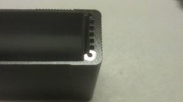
2 - scrap of the anodized material - or better use a dremel - around the lower right front screw hole
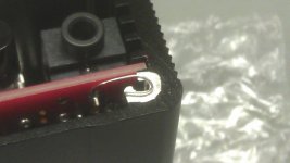
3 - bend the wire around the hole
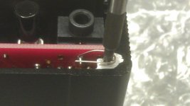
4 - step 3 works best like this 😉
now screw your front panel on and you are good to go.
Stefan
As promised, some pictures taken last night, was a bit late already and had to get up early so posting them only today. Description in order to the pics attached
1 - solder a left over lead from one of the 1/8W resistors to the ground pin of the input jack
2 - scrap of the anodized material - or better use a dremel - around the lower right front screw hole
3 - bend the wire around the hole
4 - step 3 works best like this 😉
now screw your front panel on and you are good to go.
Stefan
Attachments
Hey guys! started building my o2 amp last night, when i realized mouser sent me the wrong front panel push buttons 😕 looked into it and their stock is completely depleted and the ones they sent were close but the leads wont fit in the holes of the pcb (different size and orientation)! oh well right?
anyway the question i had was if there were any known suppliers of these guys (besides mouser) and/or if there is a know substitution for this part... the lead time is about 10 wks from mouser! 😡
thanks for any help,
-tripwire292
anyway the question i had was if there were any known suppliers of these guys (besides mouser) and/or if there is a know substitution for this part... the lead time is about 10 wks from mouser! 😡
thanks for any help,
-tripwire292
the question i had was if there were any known suppliers of these guys
Yeah I ran into that a week ago on something I'm building. Here is who stocks it http://octopart.com/partsearch#search/requestData&q=PN22SJNA03QE (hit the "more" link under the vendors for the full list).
Looks like Avnet Express, Arrow, and Onlinecomponents.com all have stock and are willing to sell in single quantities. Those vendors have other bits and pieces of the O2 BOM list. Maybe you can find some other stuff to help defray shipping. Word of warning on Arrow and Avnet through, they can ship parts from different warehouses and each incurs a shipping charge. Be sure to double check which warehouse(s) things are coming from.
Last edited:
Quick question guys, I've been trying to figure out this one for a while. For some reason, the O2 that I build's gain button is not working. Press and no press = same sound. I've read most of the thread and I don't think I've seen this problem come up before.
Any idea what might be wrong, or what I should check? (I don't have a multimeter). I have checked multiple times for lead shorts, but could not find any. Would bad soldering be causing any of the issues? I don't particularly have any bad solder spots as far as I know.
Any idea what might be wrong, or what I should check? (I don't have a multimeter). I have checked multiple times for lead shorts, but could not find any. Would bad soldering be causing any of the issues? I don't particularly have any bad solder spots as far as I know.
Quick question guys, I've been trying to figure out this one for a while. For some reason, the O2 that I build's gain button is not working. Press and no press = same sound. I've read most of the thread and I don't think I've seen this problem come up before.
Any idea what might be wrong, or what I should check? (I don't have a multimeter). I have checked multiple times for lead shorts, but could not find any. Would bad soldering be causing any of the issues? I don't particularly have any bad solder spots as far as I know.
One of the legs on the gain switch body is probably touching a pcb via or pad. Iirc back right leg if you're looking at it from the front edge of the pcb.
Thanks Shadow. Are you saying we are not supposed to solder the two diagonal legs of the switch body?
It's the left front leg on the body of the switch that comes too close to the via.
S2 PROBLEM – The September version of the PCB artwork (9/14/11 release) has the via between R21 and S2 located too close to the corner “foot” on S2. While most have not had any problem, it’s highly recommended to slightly bend the leg in that corner of the switch inward, or if you have some heavy cutters, trim that leg shorter (don’t use small “precision” cutters as you’ll likely damage the blades). At the least, make sure there is no contact when you’re soldering S2 in place.
I just solder the six pins in the middle.
Edit: Pulled out a empty pcb I have laying around to double check 😀
Thanks Shadow. Are you saying we are not supposed to solder the two diagonal legs of the switch body?
Before proceeding to solder one has to apply some sort of insulation over the via(piece of tape,girl-friend's nail polish🙂) so that the body of the switch doesn't touches the via.Since the switch is already soldered try raising it a bit(very carefully or you may damage the tracks) so that it doesn't touches the via.
BTW I've used jumpers (gain= 1X, 2X & 8X) to avoid this problem.
see #3147
http://www.diyaudio.com/forums/head...eadphone-amp-diy-project-315.html#post3377815
Last edited:
Hey guys! started building my o2 amp last night, when i realized mouser sent me the wrong front panel push buttons 😕 looked into it and their stock is completely depleted and the ones they sent were close but the leads wont fit in the holes of the pcb (different size and orientation)! oh well right?
anyway the question i had was if there were any known suppliers of these guys (besides mouser) and/or if there is a know substitution for this part... the lead time is about 10 wks from mouser! 😡
thanks for any help,
-tripwire292
You can short the appropriate points of S1/S2 & your O2 will be ON all the time(AC operation recommended) with fixed gain or I can send it to you (4 switches for 1$ plus postage) from India.
see #3147 for switches I got locally if they suit your purpose. WARNING-I didn't followed standard BOM as I'm an experienced builder myself(I repair PC/Laptop main-boards)
Last edited:
Yeah I ran into that a week ago on something I'm building. Here is who stocks it http://octopart.com/partsearch#search/requestData&q=PN22SJNA03QE...
awesome, thanks ill be checking them out tonight 😛
You can short the appropriate points of S1/S2 & your O2 will be ON all the time(AC operation recommended) with fixed gain or I can send it to you (4 switches for 1$ plus postage) from India...
if the above fails i shall pm you for more info. thanks for the offer 😛
one last thing. im going to be rewiring my hps soon. wondering if anyone has a good suggestion on a raw cable that has say 10 conductors in it and is possibly the fabric material for the sheath. thickness isnt really a big deal, just as long as its not bigger than a standard 1/4" cable.
thanks again guys 😛
-tripwire292
- Home
- Amplifiers
- Headphone Systems
- The Objective2 (O2) Headphone Amp DIY Project