schro20 said:
Now, 1uF?! Come on! Just imagine how much lower you can push the phase shift at the bottom end if you go with a 10uF coupling cap!
Size does matter! 🙂 Yep 10uF or bust!!! 🙂
peter
As for the value I'm sure you're right, it's the voltage rating that worries me...
It seems that higher the voltage, better the cap 😉
The PHE426 is polypropilene 250V, the MMK is polyester 63V...
But a nice polyester: in parallel with a 4.7uF Mundorf MCAP Zn cleaned up highs and gave a better bass too. 😎
The ApexJR cap is 250V and 10uF!ClaveFremen said:It seems that higher the voltage, better the cap 😉
peter
schro20 said:
The ApexJR cap is 250V and 10uF!
peter
But it don't fit and I want one that does...

In 22.5mm spacing I've found 4.7uF MMK 100V 😎
On the first monoblock I'll try the 10uf MMK (I've only one left...) against PHE426 and if it's better I could give a try (and buy...😉 ) also to the 4.7uF...
Gotcha!ClaveFremen said:But it don't fit and I want one that does...
Let us know how it goes (and do do a blind compare!)
peter
Help Needed
Hi All,
Well, I wired the amp to-gether with care and hooked it up to a cd player using the bulb dimmer and .... nothing from neither left nor right.
Can anybody suggest a series of checks?
I don't know where to start.
Thanks in anticipation
Hi All,
Well, I wired the amp to-gether with care and hooked it up to a cd player using the bulb dimmer and .... nothing from neither left nor right.
Can anybody suggest a series of checks?
I don't know where to start.
Thanks in anticipation
Re: Help Needed
Pictures... That is the starting place.
Test AC voltage at the BR to see if it is getting ~24VAC...
Tony X said:Hi All,
Well, I wired the amp to-gether with care and hooked it up to a cd player using the bulb dimmer and .... nothing from neither left nor right.
Can anybody suggest a series of checks?
I don't know where to start.
Thanks in anticipation
Pictures... That is the starting place.
Test AC voltage at the BR to see if it is getting ~24VAC...
Re: Help Needed
Yes. Pictures would help with some of these questions.
peter
The first thing I would do is carefully (painstakingly...) check that all the parts are where they are supposed to be and that all the electrolytic caps are connected with the correct polarity (as well as diodes and transistors). Then the more painful check: that the values or the components are correct relative to what they should be. In other words read off the rings of the resistors to make sure the right one is in the right slot. Though that's very painful. Likely checking that you have the correct supply voltages in the right places is a good thing to do before then. What about the LM318? Is it in there correctly?Tony X said:Can anybody suggest a series of checks?
Yes. Pictures would help with some of these questions.
peter
Hi,
one should get a brief dim flash at switch on when some smoothing is connected to the transformer.
Is the fuse blown?
one should get a brief dim flash at switch on when some smoothing is connected to the transformer.
Is the fuse blown?
Silmics/PIO Lightspeed Attenuator
I have tried Silmics and my ears may be different but I much prefer the Panasonics. The Silmics leave that suffocating veil on the music to me. I love the PIO caps though and if I had thought of it I might have used my PIOs on the .22uf spots as many as would fit anyway. Top/Bottom/However you can get them in there.
If you guys havent tried out a pre for this yet I have a suggestion that TOTALLY turned the tables on this amp. I used GeorgeHiFi's Lightspeed Attenuator and it blows the alps I was using out of the water. I dont know why I am going to attach it to a B1, but I have a B1 missing a diode and a resistor. When Digikey gets here I am going to do the LightspeedEctomy and remove the lightspeed from its home as it is right now and then solder it onto my B1 and see what happens.
The MyRef does require about 10k and the Lightspeed gives it 7-8k depending on your LDRs you use in it. With 96dbSPL speakers I can crank it to about 12 oclock before scaring myself but I listen at only about 8oclock. Go read about it, come back, and let me know if you need matched pairs of LDRs. I bought 100 of them and now have 120 and have a lot of matched pairs. I was going to make a 24 band equalizer with them, but its just to much work and would require buying a lot more of the LDRs to get the right number of pairs at the right resistance.
http://diyaudioprojects.com/Forum/viewtopic.php?f=12&t=388&sid=fd84c496467f1cac2b8d41b6d668f8e1
Also pics of my boards, which I had to redo as I had a mistake on them. Redone and working flawlessly.
http://picasaweb.google.com/udailey/LightspeedAttenuator#
The Lightspeed is said to completely blow away any TVC attenuators and I have used metal film stepped switched attenuators, Alps, Radio Shack 🙂, General Radio Precision Wirewound, and B1 to power my amps and this is absolutely without doubt the best.
Uriah
Coreyk78 said:... wondering if there are any capacitor locations where it would be worth it to use some boutique caps?
Reason I ask is I have some muse and silmic II caps along with a fair sized collection of Russian PIO caps, K42-Y, K40-Y, and FT-1 teflons. ...
I have tried Silmics and my ears may be different but I much prefer the Panasonics. The Silmics leave that suffocating veil on the music to me. I love the PIO caps though and if I had thought of it I might have used my PIOs on the .22uf spots as many as would fit anyway. Top/Bottom/However you can get them in there.
If you guys havent tried out a pre for this yet I have a suggestion that TOTALLY turned the tables on this amp. I used GeorgeHiFi's Lightspeed Attenuator and it blows the alps I was using out of the water. I dont know why I am going to attach it to a B1, but I have a B1 missing a diode and a resistor. When Digikey gets here I am going to do the LightspeedEctomy and remove the lightspeed from its home as it is right now and then solder it onto my B1 and see what happens.
The MyRef does require about 10k and the Lightspeed gives it 7-8k depending on your LDRs you use in it. With 96dbSPL speakers I can crank it to about 12 oclock before scaring myself but I listen at only about 8oclock. Go read about it, come back, and let me know if you need matched pairs of LDRs. I bought 100 of them and now have 120 and have a lot of matched pairs. I was going to make a 24 band equalizer with them, but its just to much work and would require buying a lot more of the LDRs to get the right number of pairs at the right resistance.
http://diyaudioprojects.com/Forum/viewtopic.php?f=12&t=388&sid=fd84c496467f1cac2b8d41b6d668f8e1
Also pics of my boards, which I had to redo as I had a mistake on them. Redone and working flawlessly.
http://picasaweb.google.com/udailey/LightspeedAttenuator#
The Lightspeed is said to completely blow away any TVC attenuators and I have used metal film stepped switched attenuators, Alps, Radio Shack 🙂, General Radio Precision Wirewound, and B1 to power my amps and this is absolutely without doubt the best.
Uriah
Help Needed
Thks replies so far.
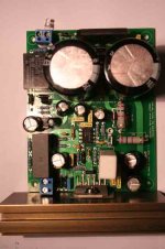
I took a lot of care when inserting the components so as not to make mistakes. I am colour-blind so resistors were handled with special care. The dimmer (20 W) does flash for a fraction of a second - I suppose as the caps are charging. I also put in an LED which just lights up - but only just.
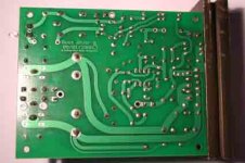
What I suspect the most is that there has been a short between the heatsink and the printed circuit on the underside of the board, altough it must be really bad luck for this to happen on the two boards at once.
I put a heatsink on the transistors while soldering.
The toroidals are rated at 24.5V, 230W.
I hope the attached photos are clear
Thks replies so far.
I took a lot of care when inserting the components so as not to make mistakes. I am colour-blind so resistors were handled with special care. The dimmer (20 W) does flash for a fraction of a second - I suppose as the caps are charging. I also put in an LED which just lights up - but only just.
What I suspect the most is that there has been a short between the heatsink and the printed circuit on the underside of the board, altough it must be really bad luck for this to happen on the two boards at once.
I put a heatsink on the transistors while soldering.
The toroidals are rated at 24.5V, 230W.
I hope the attached photos are clear
Attachments
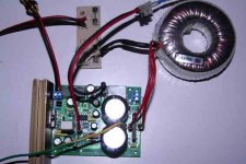
Looks like the transformer is a single secondary.. Won't work.. (unless you use 2 per channel)
Need dual secondaries or center tap..
If that transformer is >200VA and you have another you could used them both together and make a stereo unit. You would need 4 of those trafo's for mono-blocs.
Need dual secondaries or center tap..
If that transformer is >200VA and you have another you could used them both together and make a stereo unit. You would need 4 of those trafo's for mono-blocs.
Do you have the specs on the trafo?
Prolly something like:
240 primary, 24 secondary, >200VA
Needs to be:
240 primary, DUAL 24 secondaries, >200VA
or
240 primary, 24-0-24 secondary, >200VA
Prolly something like:
240 primary, 24 secondary, >200VA
Needs to be:
240 primary, DUAL 24 secondaries, >200VA
or
240 primary, 24-0-24 secondary, >200VA
Help Needed
Need dual secondaries or center tap..
O Sh---ttt. If that's the case I'll have to go looking for transformers again.
Just to try it out I can take the two I have bought (one for each board) and try them on just the one board. How should I wire them together then??
Need dual secondaries or center tap..
Looks like the transformer is a single secondary.. Won't work.. (unless you use 2 per channel) Need dual secondaries or center tap..
O Sh---ttt. If that's the case I'll have to go looking for transformers again.
Just to try it out I can take the two I have bought (one for each board) and try them on just the one board. How should I wire them together then??
Tony,
The problem is the toroid
It need 4 leads coming out of it. Right now you have 0V and 24V rather than 24/0/24.
So Troys suggestion will most likely be your solution. Use two of those transformers and twist together two of their leads so that you can make two measurements with the other leads. Take lead ABCandD. Twist BandC together. Measure from A to BC and measure from D to BC. You will want to see voltages of +24 and -24. Then take BC and take that to the ground on your boards. The wire BC should be equal to 0V.
Uriah
If it had the right primary voltage for you I would suggest this one
http://www.antekinc.com/AN-2225.pdf
notice the schematic.
Uriah
http://www.antekinc.com/AN-2225.pdf
notice the schematic.
Uriah
- Home
- Amplifiers
- Chip Amps
- The new "My Ref" Rev C thread