Just to confirm. I have k170s on q1 and sj74s on q2.
Tyerkey,
I politely suggest we follow through with my previous post. If you like I'll post drawings and diagrams to help verify a key part of your amplifier is working as designed.
Regards,
Dan 🙂

"I have 26 volts on both rails. 26 and -26."
Measure the power supply voltages by connecting the DVM black lead to the black speaker post
(for the channel you have an amplifier board installed for), and leave it there.
Do you still get both of the +/- power supply DC voltages correctly, measuring with the red DVM lead,
at the amp board? If not there is a wiring problem.
Did you use this to build it?
Firstwatt F5 amplifier v3 - diyAudio Guides
I do get 26 volts at with DMV black lead connected to the black speaker post. I only have one amp board connected at this time.
I did use the V3 power supply guide.
PS check.
Yes please. I have time and will have my laptop home over the weekend which will help me access this thread and your advice more easily. I do agree that I need to assure the power supply is actually right. I do not know where to go other than what is in the build guide for trouble shooting. So any diagrams, drawings, or instructions will be very helpful and appreciated.
Thanks
Tyerkey,
I politely suggest we follow through with my previous post. If you like I'll post drawings and diagrams to help verify a key part of your amplifier is working as designed.
Regards,
Dan 🙂
Yes please. I have time and will have my laptop home over the weekend which will help me access this thread and your advice more easily. I do agree that I need to assure the power supply is actually right. I do not know where to go other than what is in the build guide for trouble shooting. So any diagrams, drawings, or instructions will be very helpful and appreciated.
Thanks
I do get 26 volts at with DMV black lead connected to the black speaker post. I only have one amp board connected at this time.
I did use the V3 power supply guide.
The answer I'm looking for with one lead on the black speaker post is............
When the other lead is on C I get +26VDC. When I move the red lead to D I get -26VDC.
We have to get on the same page here so that you know a bipolar supply contains both a positive voltage and a negative voltage. Just saying I got 26 volts does not prove you have a properly working power supply.
More soon.
Regards,
Dan 🙂
It's important to proceed in a logical, step by step manner when troubleshooting a problem.
Otherwise conclusions may be drawn that are not valid, and considerable effort may be wasted.
Otherwise conclusions may be drawn that are not valid, and considerable effort may be wasted.
Last edited:
What does your meter say when you put one end on the green wire (on the PSU) and the other wire on the red wire (on the PSU)? Does it read 52V?
It's important to proceed in a logical, step by step manner when troubleshooting a problem.
Otherwise conclusions may be drawn that are not valid, and considerable effort may be wasted.
I couldn't agree more. After it's verified that the PS is functioning correctly I have another suggestion I think is the next logical step. Since Tyer made a small initial error with Q1 and Q2 I'd would like to check Q3 and Q4, and Q5 and Q5 for part number and orientation.
Regards,
Dan 🙂
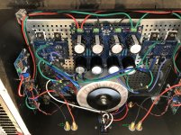
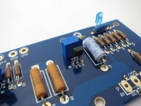
Power supply check.
I did the abcd check as described. I have attached result pics.


Or maybe not.
I did the abcd check as described. I have attached result pics.
Or maybe not.
So these all measure as expected? Is the audio board(s) still connected?
If so, repeat except measure with red DVM lead at the other ends of the PS wires, at the audio board
where they are soldered. Should have the same results.
If so, repeat except measure with red DVM lead at the other ends of the PS wires, at the audio board
where they are soldered. Should have the same results.
Last edited:
Psu voltage check.
It reads a bit over 53V
What does your meter say when you put one end on the green wire (on the PSU) and the other wire on the red wire (on the PSU)? Does it read 52V?
It reads a bit over 53V
So far your readings are perfect. I still can't see where your 'Zero volts' or 'ground' is connected through a CL-60 to the chassis. I'd like to verify that.
Regards,
Dan 🙂
Regards,
Dan 🙂

Hi all, I just found that I have Q5 and Q4 switched. Could that be the problem? Is it safe to switch them and try it?
Hi all, I just found that I have Q5 and Q4 switched. Could that be the problem? Is it safe to switch them and try it?
Do you mean Q3 and Q4 or Q5 and Q6?
Regards,
Dan 🙂
Any part in the wrong place could easily have been damaged, especially transistors.
Last edited:
After you have your MOSFETs removed there's a good YouTube video here on doing basic checks on them. That's assuming that it's your MOSFETs that were installed backwards.
How to Test MOSFET transistor using Multimeter by some easy methods - YouTube
Regards,
Dan 🙂
How to Test MOSFET transistor using Multimeter by some easy methods - YouTube
Regards,
Dan 🙂
- Home
- Amplifiers
- Pass Labs
- The most recent problem with my F5 build