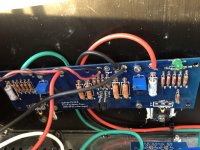
Hi all, I am still having problems with my F5 build. I still have 26 dc volts on both channels of my power supply. I believe I have the right jfets in the right places. I am working as recommended on one amp board at a time. I still have no output. No changing of the trim pots makes a difference. I get .1 mv dc across R11. I have attached pics. Any ideas other than this project was over my skill level?
Attachments

Don't count yourself out yet. The 26V on the positive rail is a good sign. What do you get on the other side (green wire) with the same red probe. Leave the black probe on ground/gnd. You should see -26V on the green wire. Can you confirm that first?
Second question - the jfets you installed, can you confirm that one is a J74 and the other is a K170 (ie, not both J74 and not both K170)
Second question - the jfets you installed, can you confirm that one is a J74 and the other is a K170 (ie, not both J74 and not both K170)
It's here:
Help please on F5 build.
and here:
Another problem with my F5 build.
And some of the same questions have been asked/answered. Like others, I haven't seen demonstrable proof that he is getting +/- 26V DC from his supply. Tom, can you show us a photo that your supplies are indeed +/- 24 to 26 volts?
Hopefully, the moderators can move these posts and stick them all in one.
Moderators please feel free to delete my post as it serves no useful purpose!
Best,
Anand.
Last edited:
tyerkey
Do the LEDs on the boards light up?
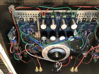
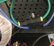
Of the three black wires leaving your PS board. Is one of them tied to a CL-60 and then the chassis? I see one spot where it may be but the pic is blocked by wires.

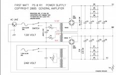
As seen on the PS schematic here.

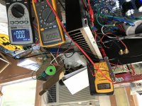
And when you measure the voltage leaving your PS board you leave the black lead in the center and move your red lead from the red wire to the green wire. That way you will get +26VDC on one side and -26VDC on the other side. Correct? I see you have a nice Fluke.
Regards,
Dan 🙂
Do the LEDs on the boards light up?
Of the three black wires leaving your PS board. Is one of them tied to a CL-60 and then the chassis? I see one spot where it may be but the pic is blocked by wires.
As seen on the PS schematic here.
And when you measure the voltage leaving your PS board you leave the black lead in the center and move your red lead from the red wire to the green wire. That way you will get +26VDC on one side and -26VDC on the other side. Correct? I see you have a nice Fluke.
Regards,
Dan 🙂
Attachments
"I have 26 volts on both rails. 26 and -26."
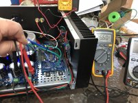
Measure the power supply voltages by connecting the DVM black lead to the black speaker post
(for the channel you have an amplifier board installed for), and leave it there.
Do you still get both of the +/- power supply DC voltages correctly, measuring with the red DVM lead,
at the amp board? If not there is a wiring problem.
Did you use this to build it?
Firstwatt F5 amplifier v3 - diyAudio Guides
Last edited:
This is the version you're building?
https://www.diyaudio.com/media/build-guides/diyaudio-f5-build-guide.pdf
Regards,
Dan 🙂
https://www.diyaudio.com/media/build-guides/diyaudio-f5-build-guide.pdf
Regards,
Dan 🙂
Sorry about starting this up in a new thread. I could not find the old one.
Top of forum, "User CP", "Your Profile", "Statistics", "Find All Posts by {you}"
Attachments

LED question
Dan, I have had no LEDs lighting up on the amp boards. I have one that works on the power supply. The other has been switched out. The resistor has been switched. I have tried the positive leg in both positions. No light. I still get -26 volts on that side.
I usually can hook up an LED without problems. I don't know what is going on here.
I am at work, so I can conform things later.
Do the LEDs on the boards light up?
Dan, I have had no LEDs lighting up on the amp boards. I have one that works on the power supply. The other has been switched out. The resistor has been switched. I have tried the positive leg in both positions. No light. I still get -26 volts on that side.
I usually can hook up an LED without problems. I don't know what is going on here.
I am at work, so I can conform things later.
PS and JFET questions
I know those are what I installed. I was very careful because I made a previous 2 errors in this spot.
I am at work, So I will have to confirm positions later.
Don't count yourself out yet. The 26V on the positive rail is a good sign. What do you get on the other side (green wire) with the same red probe. Leave the black probe on ground/gnd. You should see -26V on the green wire. Can you confirm that first?
Yes, Confirmed.
Second question - the jfets you installed, can you confirm that one is a J74 and the other is a K170 (ie, not both J74 and not both K170)
I know those are what I installed. I was very careful because I made a previous 2 errors in this spot.
I am at work, So I will have to confirm positions later.
Version
This is the version you're building?
Yes. But my power supply is version 3. That led to some earlier confusion for me.
tyerkey
Do the LEDs on the boards light up?
Of the three black wires leaving your PS board. Is one of them tied to a CL-60 and then the chassis? I see one spot where it may be but the pic is blocked by wires.
As seen on the PS schematic here.
And when you measure the voltage leaving your PS board you leave the black lead in the center and move your red lead from the red wire to the green wire. That way you will get +26VDC on one side and -26VDC on the other side. Correct? I see you have a nice Fluke.
Regards,
Dan 🙂
Yes on both. The CL60 is behind the shrink wrapped blue and green wires.
The power supply ground connections to the audio board must be open/wrong if the PS board LEDs work.
Measure the power supply voltages by connecting the DVM black lead to the black speaker post
(for the channel you have an amplifier board installed for), and leave it there.
Do you still get both of the +/- power supply DC voltages correctly, measuring with the red DVM lead,
at the amp board? If not there is a wiring problem.
Last edited:
Let's go through the PS very carefully step by step until we're 100% sure it's working properly. Why? Because without correctly working power nothing will work and it will make you second guess stuff that is installed properly.
Regards,
Dan 🙂
Regards,
Dan 🙂
- Home
- Amplifiers
- Pass Labs
- The most recent problem with my F5 build