Oh , I was not going to do a single supply." Lifting" the loudspeaker grounds would leave the voltage stage ground, main star cap ground, It is the same as breaking the amp output with the relay (it is still in the signal path.) Don't worry ,I am conventional. I will still have a 60-0-60 and a 68-0-68 (notice the 0). with a large enough relay , doing it either way would suffice (separate relay board with euroconnects).
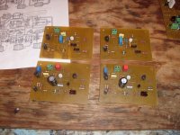
Tommorrow I build the actual "new" AX's and EX's (barn amps) ... the PCB's are drilled and tinned. 🙂 😎 many pix !!
OS
Tommorrow I build the actual "new" AX's and EX's (barn amps) ... the PCB's are drilled and tinned. 🙂 😎 many pix !!
OS
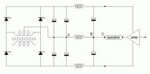
Here is the schematic. If the relay is betwen the speaker and the ground the relay is in the signal path if the relay is betwen point A and point B the relay is not in signal path.
At this point of the circuit we may also monitor for DC current in speaker.
At this point of the circuit we may also monitor for DC current in speaker.
Attachments
Here is the schematic. If the relay is betwen the speaker and the ground the relay is in the signal path if the relay is betwen point A and point B the relay is not in signal path.
At this point of the circuit we may also monitor for DC current in speaker.
A/B was just the position I was thinking. My amp is not like the typical. "The amp" you have pictured is just my to-3p output devices and 2 local decoupling caps. the rest of the amp-VS/IPS (drivers included) is totally isolated from "the amp" you have shown.
OS
There are 2 possible failure modes
arcs closed = blows rail fuse or speakers or both (to do that to a 20A relay would be a case of ultimate abuse or just bad luck)
Fails in general (opens /or the coil burns) = still safe.
OS
arcs closed = blows rail fuse or speakers or both (to do that to a 20A relay would be a case of ultimate abuse or just bad luck)
Fails in general (opens /or the coil burns) = still safe.
OS
A/B was just the position I was thinking. My amp is not like the typical. "The amp" you have pictured is just my to-3p output devices and 2 local decoupling caps. the rest of the amp-VS/IPS (drivers included) is totally isolated from "the amp" you have shown.
OS
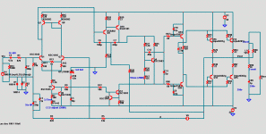
I read all the thread day after day and found it very interesting and I did notice the special power supply configuration, but last night it was very very late so I made just a section of the schematic but giving enough to make it clear ....
International standards? Prosound use?
My preference is to switch the speaker the traditional way (at speaker output), with one exception:
Double-up contacts for redundancy. With a pair of dpst relays at speaker jack, it can be arranged redundant so that both speakers play even if one relay fails completely.
Traditional + redundancy is better because:
1). No contact bounce (contacts are redundant)
2). No confusion during assembly (international standards met easily)
3). No failures from pro sound transportation in a Hot Humid van or bus. (relays are redundant)
4). No failures from 4 ohm current handling (if soundman daisy chains speakers)
So, how do you want your relays--Will AX rock out the gig or will the party be over before it starts?
19 years
The amp the AX is replacing (nikko alpha 230) blasted away at block parties in Brooklyn, NY for almost 2 decades with a single 2 X 15A omron relay. I have that relay and will use it for the ax. If that is not industrial abuse , I don't know what is ??
OS
The amp the AX is replacing (nikko alpha 230) blasted away at block parties in Brooklyn, NY for almost 2 decades with a single 2 X 15A omron relay. I have that relay and will use it for the ax. If that is not industrial abuse , I don't know what is ??
OS
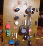
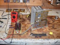
AX and EX almost done..
More etching and a drillin' to get my amps back. Better than the last batch (below). I am leaving the IPS's and the VAS to match the pairs tomorrow. I have a huge pile of mje340/50's - ksa1381/sc3503's - ksc1845's (over 200 devices) , I should be able to find some real close "mates". 😀
Front amps are the AX's (2 Cdoms together/ front) and the EX (supersym 3) behind . It is my "KIS" amp , much like the famous goldmund , only 8 devices in the VAS/IPS.
OS
Attachments
The amp the AX is replacing (nikko alpha 230) blasted away at block parties in Brooklyn, NY for almost 2 decades with a single 2 X 15A omron relay. I have that relay and will use it for the ax. If that is not industrial abuse , I don't know what is ??
OS
Well, the method that lasted 19 years, seems to be the right way to do it.
That long term test success, is valuable and desirable.
It works !!!
(Below 1) is the backwards way I run just the drivers as a small amp (I hate to waste good outputs 😀 )
PS - see the burnt 22R resistors , I had a C-E solder bridge on one of the drivers and this amp did not blow up !! even burnt .. they still read 22R ... so I used them anyways ..
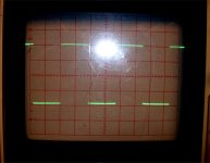
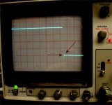
(below 2) is the nice 40 p-p (10v/div) squarewave that those drivers put out into 22R loads fed back to NFB.
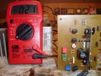
(Below 3) is the new (and final) AX module. I switched my CRO to 1uS/div and the SW rises all 40 V in half a division (70-80 V/uS slew estimate).
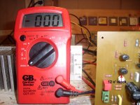
(below 4) is offset with the trimmer at 2 O' clock , I get 25mV only by "mistuning" ... I have NO idea how the goldmund clone or any other amp can't get 5-10 mV right off the bat (first try ???).
(below 5) is the offset (what offset ?) at real close to 12 O'clock , perfect as it should be. Input pair CCS is 7 volts across 2200R (3.18mA total -1.59mA each) VAS CCS is 605mV across a 100R (6.05mA) Perfectly predicted by LT. Slew rate is more than LT predicted 😎 .
OS
(Below 1) is the backwards way I run just the drivers as a small amp (I hate to waste good outputs 😀 )
PS - see the burnt 22R resistors , I had a C-E solder bridge on one of the drivers and this amp did not blow up !! even burnt .. they still read 22R ... so I used them anyways ..
(below 2) is the nice 40 p-p (10v/div) squarewave that those drivers put out into 22R loads fed back to NFB.
(Below 3) is the new (and final) AX module. I switched my CRO to 1uS/div and the SW rises all 40 V in half a division (70-80 V/uS slew estimate).
(below 4) is offset with the trimmer at 2 O' clock , I get 25mV only by "mistuning" ... I have NO idea how the goldmund clone or any other amp can't get 5-10 mV right off the bat (first try ???).
(below 5) is the offset (what offset ?) at real close to 12 O'clock , perfect as it should be. Input pair CCS is 7 volts across 2200R (3.18mA total -1.59mA each) VAS CCS is 605mV across a 100R (6.05mA) Perfectly predicted by LT. Slew rate is more than LT predicted 😎 .
OS
Attachments
Last edited:
Well done !
Your slew rate is even faster.
You measure just 90% of the voltage rise and use that 90% time value to calculate SR.
One of the best threads around for the balance between: designing, simulating, building, debugging, setting up to work properly.
Very informative and should be required reading for all newcomers.
When do we introduce a "test" for new and existing Members to raise them to accredited status?
Let's get rid of that "star" that members can buy.
The test could be based on the simpler parts from: Pass, Self, OST, Cordell, Leach, Davenport papers. Then we know that an accredited "Analogue Member" has read these as a starter. It should only appear in "profile"
Last edited:
Well done !
One of the best threads around for the balance between: designing, simulating, building, debugging, setting up to work properly.
Very informative and should be required reading for all newcomers.
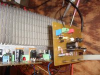
Thanks Andrew , I have built these before but I thought I would show yet again how I avoided burning parts
 . IF I had the outputs hooked to this thing at first test , I would of ended up losing 2 or all four devices (10$) 🙁
When I was pulling my hair out (dead amp with smoking Re's on first test) , I also ran the voltage module by itself. Just hook 2 390R's from the +/- drives to a NFB point and the AX module will run by itself. At that point, I knew it was the power module (vbe or drivers ?? ).
I am still learning the "finer points" but have the basics down pat (100% from LT to finished product). PS ... I ran the 40V 20khz SW ALL night ... It (the amp) still lives this morning (drivers are a little warm 😀 ). Test complete !! Also , first pix last post - see the 4.7R safety resistors on the left near the PS ? .. absolutely essential !!
OS
Last edited:
Let's get rid of that "star" that members can buy.
Andrew - with all due respect to you sir (and I do respect you) that "star" is an indicator of those who have seen fit to donate funds with which to help diyAudio keep doing what it does. It does take money to host this site and keep it running. I get a great deal of enjoyment reading and learning from the threads here and those (such as yourself and OS for example) who contribute knowledge. So we are both contributors and thus help things along. I would agree that perhaps something like a $$$ symbol for financial supporters might be more fitting and you could have something to indicate the level of a persons knowledge - but then who would you suggest run that little certification program?
Donating is good , I might have to do so - sick of emptying my messages out 😀 .
To pay the bills , it is required. Selling esoteric parts $$$ in the commercial section is needed, too. I have done extensive testing with "better parts" in class AB amps. Some improve the electrical tests of the amp , so a "better part"... I believe, can improve the sound. Using 1% emitter resistors can achieve <1mv offset and perfect input pair balance resulting in better sound. A thicker wire CAN reduce inductance, therefore eliminating that parasitic from the circuit.
I will share the final AX (below - exact real board values). I still can't figure why the slew is so much faster than the sim predicts ... but it is. 😕
Listening should be glorious ... this amp should "loaf" through any complex source put to it's input. 🙂
OS
Attachments
Last edited:
Pn post 1515 there is a pair of cap multipliers and on post 1638 they flew away.
I think it was a better configuration with cap multipliers
i you put boards or kits for sale will you put them back ??? or leave no isolation betwen output supply and input supply ??
I think it was a better configuration with cap multipliers
i you put boards or kits for sale will you put them back ??? or leave no isolation betwen output supply and input supply ??
That's just the base design for the AX without the multipliers (for testing).
All my powerboards will have the multipliers as well as the integrated board. The only board without will be my (R & D) PB60 , which I will remake to take right angle modules. I want to make a "breakaway" 4 OR 8 device universal powerboard just for flat "pro" installations . I feel aluminum angle is adequate but not "pro" , all the high current amps I have seen are direct thermal solutions.
Cheap OEM sony's have spotwelded fin heatsinks , My Nikko is in the middle with it "skived" heatsinks (all 1 extrusion) , then the Hafler's,yamaha's,and other pro amps with their huge single extrusion.
I will make the 120w integrated version for angle mounting.
OS
The part I am scared of .... power test
It totally works !!!
I started with the safety resistors in (4.7R 1/2w). With the bias at full resistance , my outputs were biased class B (0 mV Re). 2 turns - 5mV Re 4 turns - 12mV re (Re= .22R). Safety resistors confirmed .74V drop per rail {.74/4.7 = 158 mA) , I would assume 60mA X 2 (outputs) + 38mA for the cap MUX/drivers and AX module.
Then I was at the real test (goodbye safety resistors -power SW test). (below 1) is the 95W/10R resistor and the "junk supply". Resistor became too hot to touch after a minute.
10Khz square wave is still very fast .... but has a damped overshoot (below 2) ???😕 . Ran the 10R resistor into a big 10uF cap and the overshoot "ringing" was larger but still damped. Cold Zoble , total flatline (0 V) with no input , absolutely stable 12-14 mV Vbe even after temperature cycling. Without the load , there was no overshoot. Is this normal ? , I have never done a real world torture test before (had no 95w resistor). I also ran this test with no output L/C (1.5uH/10R network).
It's still "burning away" in the shop (below 3) ... maybe I'll let it burn all night 😀 .
OS
It totally works !!!
I started with the safety resistors in (4.7R 1/2w). With the bias at full resistance , my outputs were biased class B (0 mV Re). 2 turns - 5mV Re 4 turns - 12mV re (Re= .22R). Safety resistors confirmed .74V drop per rail {.74/4.7 = 158 mA) , I would assume 60mA X 2 (outputs) + 38mA for the cap MUX/drivers and AX module.
Then I was at the real test (goodbye safety resistors -power SW test). (below 1) is the 95W/10R resistor and the "junk supply". Resistor became too hot to touch
after a minute.10Khz square wave is still very fast .... but has a damped overshoot (below 2) ???😕 . Ran the 10R resistor into a big 10uF cap and the overshoot "ringing" was larger but still damped. Cold Zoble , total flatline (0 V) with no input , absolutely stable 12-14 mV Vbe even after temperature cycling. Without the load , there was no overshoot. Is this normal ? , I have never done a real world torture test before (had no 95w resistor). I also ran this test with no output L/C (1.5uH/10R network).
It's still "burning away" in the shop (below 3) ... maybe I'll let it burn all night 😀 .
OS
Attachments
It totally works !!!
10Khz square wave is still very fast .... but has a damped overshoot (below 2) ???😕 . Ran the 10R resistor into a big 10uF cap and the overshoot "ringing" was larger but still damped. Cold Zoble , total flatline (0 V) with no input , absolutely stable 12-14 mV Vbe even after temperature cycling. Without the load , there was no overshoot. Is this normal ? , I have never done a real world torture test before (had no 95w resistor). I also ran this test with no output L/C (1.5uH/10R
OS
I've only had the overshoot ring with a 2nd cap parallel to the load resistor. No ringing into 3, 4, 8 ohm loads. My setup was fairly conventional. Single pole compensation lme49811 front end, modular design like yours.
I tried the amp at 60V p-p with no load , the slight overshoot is still apparent (below 1). The overshot edges are where the ringing occurs. Should there be no overshoot ? Driving the 10uF capacitor did not produce much more ringing (well damped). The slew in the pix is way over 80V/us (more like 100V+) , is this why I get the overshoot (too fast ??). The AX board has every compensation scheme designed into the layout. Extra pad for lead compensation (vas or NFB) , miller comp. , TMC , TPC ... everything (universal blameless). Maybe if I play with the TMC feedback or add a little lead comp ???? will play with it. Still a few parts short of final assembly , but I have major points nearly finished (a working amp) 🙂
OS
OS
Attachments

- Home
- Amplifiers
- Solid State
- The MONGREL (supersym II)