Oh, I can blame you! I had a picture saved that I was using to reference the build as seen in post # 448.
Just kidding, I should have double checked the pinouts myself.
I'll get to testing later tonight however it looks like the transistor is ok. I don't have any more 2SA992's here otherwise I would replace it as a precaution, and they are difficult to get in Australia.
Pete.
Just kidding, I should have double checked the pinouts myself.
I'll get to testing later tonight however it looks like the transistor is ok. I don't have any more 2SA992's here otherwise I would replace it as a precaution, and they are difficult to get in Australia.
Pete.
Ok, one channel is working just need to tweak the pots now, I have 20mv on the .22r resistors even with them wound out to 200r. Haven't had chance to do any more with it though.
The other channel still has the same problem. Looks like the transistor might be shot.
Getting closer though.
Pete
The other channel still has the same problem. Looks like the transistor might be shot.
Getting closer though.
Pete
You can use any PNP- ECB pinout like 2sa970 . Just look for Hfe 200-400 and 100-120v Vceo. I just use these as they are $13 per hundred for 1845/992's here. If you are all the way out on the Vbias it mean your ccs is maladjusted , it should be half way (100r = 3.5ma tail current)
OS
OS
Just went back to it and found r26 showing 40r. I found a trace shorted and fixed it. Now getting correct readings.
The first channel is now reading ok on vbias, not sure what happened there??? Had 10 mv with it wound out to 200r and adjusted it to 15mv for now. I still need to check over it properly, for now I'm happy to see these results.
Pete
The first channel is now reading ok on vbias, not sure what happened there??? Had 10 mv with it wound out to 200r and adjusted it to 15mv for now. I still need to check over it properly, for now I'm happy to see these results.
Pete
Source for 2S transistors
Hi,
I am running out of the 2sa970/c2240 as I only have transistors salvaged from an old amp.
Today I found a supplier in Thailand(Tayda Electronics Home Page) and they stocks KTA1268GR & KTC3200GR. They are manufactured by KEC and the spec looks very similar to 2SA970/C2240. It cost 9c each and the shipping is very reasonable. I ordered a bunch of them.
BTW, they also stock Renesas 2SJ162 & 2SK1058 LFET for $3.50 each. The local Jaycar Electronics are selling these at $23.50 each.
I could not find matching VAS transistors from this site.
Cheers, Stanley
You can use any PNP- ECB pinout like 2sa970 . Just look for Hfe 200-400 and 100-120v Vceo. I just use these as they are $13 per hundred for 1845/992's here.
OS
Hi,
I am running out of the 2sa970/c2240 as I only have transistors salvaged from an old amp.
Today I found a supplier in Thailand(Tayda Electronics Home Page) and they stocks KTA1268GR & KTC3200GR. They are manufactured by KEC and the spec looks very similar to 2SA970/C2240. It cost 9c each and the shipping is very reasonable. I ordered a bunch of them.
BTW, they also stock Renesas 2SJ162 & 2SK1058 LFET for $3.50 each. The local Jaycar Electronics are selling these at $23.50 each.
I could not find matching VAS transistors from this site.
Cheers, Stanley
go to the last plot in this link
KTA1268 pdf, KTA1268 description, KTA1268 datasheets, KTA1268 view ::: ALLDATASHEET :::
It shows that you should keep the Ic of this device between 0.4mA and 9mA.
Look also at the noise plots for both 10Hz and 1kHz.
This device performs at high Ic. Probably does well from 2mA to 5mA for best noise from a low source impedance.
If you could get BL grade for lower input offset current.
insist on a money back warranty for genuine/fake LmosFETs and return postage at their cost.
If they refuse those conditions then don't buy.
If they refuse those conditions then don't buy.
Tayda
Thanks Andrew,
Their website looks quite professional & I googled & could not find any negative reviews on Tayda. I checked their ebay store & they have 100% positive feedback out of 9600 transactions.
They do have a refund policy:
"All our products are brand new. We import 95% of our inventory direct from manufacturers. We provide manufacturer names, manufacturer part numbers and datasheets for all the products listed in our online store.
Buy with confidence. We sell all our products with 100% satisfaction guarantee, any damaged or malfunctioning product will be fully refunded including shipping costs without any hassle."
I need more 2S types (ECB pinout) SSTs, so I bought $43 worth of parts & the shipping is only $5.40. They calculate the shipping by weight: approximately 1.3c per TO92 & 10c per TO264 device.
Cheers, Stanley
insist on a money back warranty for genuine/fake LmosFETs and return postage at their cost.
If they refuse those conditions then don't buy.
Thanks Andrew,
Their website looks quite professional & I googled & could not find any negative reviews on Tayda. I checked their ebay store & they have 100% positive feedback out of 9600 transactions.
They do have a refund policy:
"All our products are brand new. We import 95% of our inventory direct from manufacturers. We provide manufacturer names, manufacturer part numbers and datasheets for all the products listed in our online store.
Buy with confidence. We sell all our products with 100% satisfaction guarantee, any damaged or malfunctioning product will be fully refunded including shipping costs without any hassle."
I need more 2S types (ECB pinout) SSTs, so I bought $43 worth of parts & the shipping is only $5.40. They calculate the shipping by weight: approximately 1.3c per TO92 & 10c per TO264 device.
Cheers, Stanley
Last edited:
Just went back to it and found r26 showing 40r. I found a trace shorted and fixed it. Now getting correct readings.
The first channel is now reading ok on vbias, not sure what happened there??? Had 10 mv with it wound out to 200r and adjusted it to 15mv for now. I still need to check over it properly, for now I'm happy to see these results.
Pete
Did you know you can adjust the range of the Vbias ,(Vbe) by adjusting "CCS adj.".
Depending on your output type, .. having "ccs adj." at 100-115R should make Vbias (200r) ,go to the middle (80-100R) for 10-12mv across your 0R22's (proper bias current/ 50-60ma).
OS
Thanks Oz and Stanley, it's all up and running now. I'm really happy with the results.
Love the modular design, it helped a lot with my troubleshooting.
As for your above comment, I trimmed the CCS to get 255mv across r8 instead of the 300mv that I originally had and just as you said, the vbias trimmer is now central. (I do have a resistance of r175 on the r6 to get this though, with it set at r100 I was getting around 320mv across r8).
Thanks again,
Pete.
Thanks Oz and Stanley, it's all up and running now. I'm really happy with the results.
Love the modular design, it helped a lot with my troubleshooting.
As for your above comment, I trimmed the CCS to get 255mv across r8 instead of the 300mv that I originally had and just as you said, the vbias trimmer is now central. (I do have a resistance of r175 on the r6 to get this though, with it set at r100 I was getting around 320mv across r8).
Thanks again,
Pete.
Very good , glad to be of assistance. Stay tuned to GX upgrades , I actually have learned more since i designed it. 😎
OS
At it again - Sprint layout level 2
Am going to go for broke , wife says i'm a crazy perfectionist... but so what.
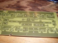
Attachment (pix) 1 - The sprint board layout (PB250BJT- HOS) MY board.. VERY fat rails/ fuses - rail fastons in the middle. 2nd order capacitance multiplier , onboard Vbe. A VERY durable , straitforward EF2 modular PCB.
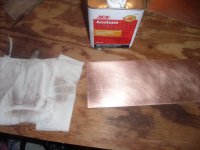
Pix-2 - You really have to ultra clean the board , remove any edge "burrs" , sand with 220/300 grit then double clean (acetone or pure alcohol) till you get NO grime on your towels.
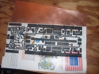
Pix-3 - Ready to print , set your HP (best toner 272c melting point) to MAX toner use "5" in the HP printer properties. Attach a glossy magazine page to a standard sheet of printer paper with a piece of scotch tape in the middle. try not to print on the tape. Line up board on top of board corner iron down hard to tack lined up magazine to PCB ... flip over and iron the hell out of it , pressing hard - use a thin paper towel/ napkin between iron and image.
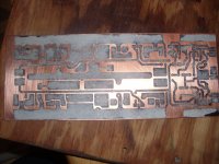
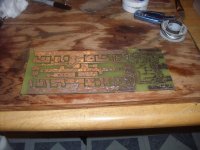
Pix-4 - toner image is re-fused with paper soaked in soapy water and lightly rubbed off , you can leave paper fibers on large tracks ... just check small gaps between small components - no paper there. Tip -you can just lightly scrape holes.
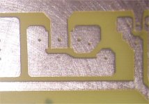
pix-5 - I defy the people that say toner transfer is sloppy , if you practice .. it can be glorious. Lines are very straight , hex pads are hex very fine lines between to-126's are perfect with NO bridges. Heat your etchant in hot water , it took me 200 seconds to "burn this board" (HCL/H2O2).
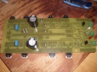
Pix - 6 - Completed power board ready for stuffin' .. I tin using lead free 50/50 copper tin plumbers solder , apply flux tin , clean with window cleaner/hot water , all ready to go. These mouser FR-4's are bulletproof - you CAN NOT lift a pad with a soldering iron , even minutes.
MUCH, MUCH more to come , big sheet of FR-4 😀 🙂🙂
OS
Am going to go for broke , wife says i'm a crazy perfectionist... but so what.
Attachment (pix) 1 - The sprint board layout (PB250BJT- HOS) MY board.. VERY fat rails/ fuses - rail fastons in the middle. 2nd order capacitance multiplier , onboard Vbe. A VERY durable , straitforward EF2 modular PCB.
Pix-2 - You really have to ultra clean the board , remove any edge "burrs" , sand with 220/300 grit then double clean (acetone or pure alcohol) till you get NO grime on your towels.
Pix-3 - Ready to print , set your HP (best toner 272c melting point) to MAX toner use "5" in the HP printer properties. Attach a glossy magazine page to a standard sheet of printer paper with a piece of scotch tape in the middle. try not to print on the tape. Line up board on top of board corner iron down hard to tack lined up magazine to PCB ... flip over and iron the hell out of it , pressing hard - use a thin paper towel/ napkin between iron and image.
Pix-4 - toner image is re-fused with paper soaked in soapy water and lightly rubbed off , you can leave paper fibers on large tracks ... just check small gaps between small components - no paper there. Tip -you can just lightly scrape holes.
pix-5 - I defy the people that say toner transfer is sloppy , if you practice .. it can be glorious. Lines are very straight , hex pads are hex very fine lines between to-126's are perfect with NO bridges. Heat your etchant in hot water , it took me 200 seconds to "burn this board" (HCL/H2O2).
Pix - 6 - Completed power board ready for stuffin' .. I tin using lead free 50/50 copper tin plumbers solder , apply flux tin , clean with window cleaner/hot water , all ready to go. These mouser FR-4's are bulletproof - you CAN NOT lift a pad with a soldering iron , even minutes.
MUCH, MUCH more to come , big sheet of FR-4 😀 🙂🙂
OS
Attachments

OOOH! I like pictures 😉
Beauty of a board OS. Your layout skill has improved by considerable margin.

Beauty of a board OS. Your layout skill has improved by considerable margin.
OOOH! I like pictures 😉
Beauty of a board OS. Your layout skill has improved by considerable margin.
Thanks , John. We have to be "men of action". I WILL lay the whole goldmund thing to rest , I have a lateral board and the CX (goldmund killer) on the table next.
BTW , here is the tinnin' (below)
OS
Attachments
My boards bend when I tin them 🙁
Mine do a little (large ones) , just use a weight to bend them the opposite way overnight.
Smaller (BX,CX voltage boards) bend VERY little , usually recover perfectly within a hour. 🙂
OS
Everything fits !!
Very pleased with these PB's , too tired to continue. This PCB is the first to have the semi's under the board. With the thick tinning and this bulletproof FR-4 ,my fear of the NJW21193/4's burning the board are most likely unwarranted.
OS
Very pleased with these PB's , too tired to continue. This PCB is the first to have the semi's under the board. With the thick tinning and this bulletproof FR-4 ,my fear of the NJW21193/4's burning the board are most likely unwarranted.
OS
Attachments
Hi os,
In your ,ac... simulation what is correct way to conect TMC resistor, direct to outut as in yu do or after AC1(BX1.3) close to R5?
dado
In your ,ac... simulation what is correct way to conect TMC resistor, direct to outut as in yu do or after AC1(BX1.3) close to R5?
dado
Hi os,
In your ,ac... simulation what is correct way to conect TMC resistor, direct to outut as in yu do or after AC1(BX1.3) close to R5?
dado
A picture tells a million stories... (below)
If you hook like picture you will see true global loop gain. If before AC1 you will see the TMC correction loop gain bode.
OS
Attachments

Last edited:
- Home
- Amplifiers
- Solid State
- The MONGREL (supersym II)