Did it bias correctly?? , I have only used mine at 75 volt rails.
OS
Hi OS,
I use 42V rails and I used your suggested values for less than 50V rails:
R21, R22 = 3.3K; R16=18K. I have no problem with the bias.
I also preferred the BC & 2N SSTs as they are easier to source & cheaper in Australia.
I have to use recycled SSTs for this build:
Q1 & Q2 - BC550 (Fairchild)
Q3, Q4, Q7 & Q8 - 2SC2240 (used - salvaged from an old JVC amp)
Q5, Q6 & Q9 - 2SA970 (used - salvaged from an old JVC amp)
Q10 - 2SA1360 (Toshiba)
I used parts available in my parts bin:
C2 & C7 are Wima FKP2 Polypropylene
C9 - EPCOS B41828 series 100uF 50V
BTW, The labels for Q7 & Q8 are still wrong (Q8 should be closer to the CCS trimpot) but they are the same type so it does not matter much.
Cheers, Stanley
Attachments
I guess.... I guessed right. 😀
That is beautiful .. man ! I can't wait till I get these boards made , you even had the same 1381 heatsink I designed for and it fits !!! I am using the old BX1.1 boards now and yours are nicer.. 😱 I am going to give C6 a little more room... (update)
OS 😎😎
That is beautiful .. man ! I can't wait till I get these boards made , you even had the same 1381 heatsink I designed for and it fits !!! I am using the old BX1.1 boards now and yours are nicer.. 😱 I am going to give C6 a little more room... (update)
OS 😎😎
Last edited:
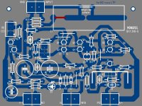
BX1.3 is a "world board".
Added better universal input cap layout and a second PCB jpg. to accommodate
BC556 or similar (BX1.3VB_BCxxx.jpg). It is included in the .zip. Now , since it is cascoded , it can accept ANY fet or BJT to-92 device. Also , C6 has some extra "leg room".
OS
Added better universal input cap layout and a second PCB jpg. to accommodate
BC556 or similar (BX1.3VB_BCxxx.jpg). It is included in the .zip. Now , since it is cascoded , it can accept ANY fet or BJT to-92 device. Also , C6 has some extra "leg room".
OS
Attachments
sorry, got that wrong!!!
understand now.
Saw the link and thought that was to by-pass the cap
understand now.
Saw the link and thought that was to by-pass the cap
Last edited:
Help!!!
Hi Os
I've finally got back to my GX/PB120 build, and am having some difficulty setting it up.
Firstly, I can't get any voltage reading across the .22r resistors on the output board.
Secondly on the GX board, I'm only getting 127mV across r19/25 and 0v across r20/24.
My psu is only +/-39v if this makes any difference.
Looking at post # 651 on page 66, I am getting -0.668mv and -0.703mv across the emitters of Q1/2 and 0.625mv across the base of Q3/4.
Voltage across r22 is 74.5v with ~ 39v rails
PD+ 0.910mv ND- 0.920mv
I'm getting identical results on both channels and I've checked over the circuit board but can't see any mistake but I must be missing something.
I'm not sure where to go next?
Much thanks
Pete
Hi Os
I've finally got back to my GX/PB120 build, and am having some difficulty setting it up.
Firstly, I can't get any voltage reading across the .22r resistors on the output board.
Secondly on the GX board, I'm only getting 127mV across r19/25 and 0v across r20/24.
My psu is only +/-39v if this makes any difference.
Looking at post # 651 on page 66, I am getting -0.668mv and -0.703mv across the emitters of Q1/2 and 0.625mv across the base of Q3/4.
Voltage across r22 is 74.5v with ~ 39v rails
Pete
Hi Pete,
Most of the voltage reading looks fine to me.
I think that you need to adjust the three trimpots to get the following voltage reading:
To start off, remove power and pre-adjust the trimpot to have following resistance:
R12 (Offset Adjust) = 250R (12.5 turn from one end of the adjustment when you hear the clicks)
R27 (Level Adjust) ~ 54R
R6 (CCS Adjust) ~ 105R
Adjust R6 until you get about 300mV across R8 (100R)
Other voltage reading with 42V rails.
Base of Q1 = -0.720V
Base of Q2 = -0.707V
Emitter of Q3 = 6.71V
Emitter of Q4 = 6.71V
Voltage across R22 = 76.9V
Voltage across R24(33ohm) = 239mV
Voltage across R25(68ohm) = 630mV
Then you can adjust the trimpot on the PB120 until you get the desired bias current on the output transistors. I have around 15mV across the 0.22R resistor but they vary by a couple of mV.
Good luck with your GX.
Cheers, Stanley
Thanks Stanley, The problem is I can't get any voltage reading across r24 and the vbias just reads 0v no matter where the trim is set.
Emitter volts on Q3/4 is 6.1v
Base of Q1 is -80mv and Q2 is 19mv which seem way off.
Any thoughts???
Pete
Emitter volts on Q3/4 is 6.1v
Base of Q1 is -80mv and Q2 is 19mv which seem way off.
Any thoughts???
Pete
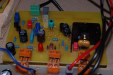
GX1.2 VB Photo
Pete,
Concentrate on the GX1.2 voltage board as the base voltage of Q1 & Q2 does not look right to me. Check the transistor types & the resisters value against the schematics AND BOM AND the Overview diagram, (YES, triple-check & sometime you will find some inconsistencies).
I eyeballed my GX-VB, the flat-side of the green LEDs are facing away from each other - the flat side facing the nearest PCB edge. Both Green LEDs should be dimly lit.
What type of transistors are you using? Post a list here & see if we can spot something.
I attached a picture of my GX-VB so that you can compare against yours.
Cheers, Stanley
Attachments
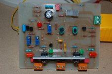
Another pix...

I also can plug my GX's back in to get voltage readings. Or , my simulation of it is within 1% of the real values.
BTW , I am going to give the GX a "facelift" , it's a good amp.
OS
I also can plug my GX's back in to get voltage readings. Or , my simulation of it is within 1% of the real values.
BTW , I am going to give the GX a "facelift" , it's a good amp.
OS
Hi OS,
Will these boards ( at least input boards) be available or do we have to make our own PCBs?
I am very interested in making an Cx and Gx.
Will these boards ( at least input boards) be available or do we have to make our own PCBs?
I am very interested in making an Cx and Gx.
Thanks guys, I'll check over again tomorrow. All the LED's light up but will double check all components as you have suggested. Whatever the error is, I have done it on both boards.
Pete.
Pete.
I also can plug my GX's back in to get voltage readings. Or , my simulation of it is within 1% of the real values.
BTW , I am going to give the GX a "facelift" , it's a good amp.
OS
Hey OS
Where do you get those pretty blue power connects and pots? EBAY?
Thanks guys, I'll check over again tomorrow. All the LED's light up but will double check all components as you have suggested. Whatever the error is, I have done it on both boards.
Pete.
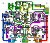
If both green leds light up your cascode works , make sure you did not do as me and confirm that you have NFB from the output to the nfb terminal. I still have the original layout/ overview of the GX (below) , even as I will soon give it a "facelift".
Krisfr , all my trimpots and euro-connects are from mouser , I buy whatever is the best deal , some are blue/green/black.
OS
Attachments
Thanks guys, I'll check over again tomorrow. All the LED's light up but will double check all components as you have suggested. Whatever the error is, I have done it on both boards.
Pete.
Hi Pete,
Don't forget the links. I also made a stupid mistake when I tried to adjust the CCS current - I adjusted the wrong trimpot; The CCS trimpot is the second one from the left.
Good luck with your trouble-shooting.
Cheers, Stanley
Mouser does not list euro-connect
Sorry, do you have another name or part.
Thanks
Hi,
I looked up the Mouser paper catalog, I found at least two parts:
538-39880-0302 Molex Eurostyle Terminal Blocks
571-2828372 Tyco Fixed Terminal Blocks 5.08MM PCB MOUNT 2P
Phoenix Contact also work but you have to select the correct mounting pitch & mounting style.
Cheers, Stanley
Ah-ha! Looks like I have Q7 upside down compared to your photos.
Pete.
I did that too , but did not power the circuit up. replace that tranny .. it might be toast.
 If your trimmers are new they should be centered (200r will be at 100r - in the middle) , this is almost perfect for CCS adj. . the offset adj is not as critical and will not cook your amp , but make sure your Vbias for the output stage is set at its max (200r). This will underbias the output stage until you adjust for 12-15 mv across the big .22R emitter resitors (50-80mA per device) . 🙂
OS
- Home
- Amplifiers
- Solid State
- The MONGREL (supersym II)