I also thought the SS9012/9013 were interesting. The 9014's might be a really good low noise VAS.
So where can I find these Baxandall papers?
- keantoken
So where can I find these Baxandall papers?
- keantoken
I also thought the SS9012/9013 were interesting. The 9014's might be a really good low noise VAS.
So where can I find these Baxandall papers?
- keantoken
Baxandall papers -
The Baxandall Papers: Transitional Miller compensation
SS9014/15 = low Vceo ... maybe a "iddy bitty" amp OR in a cascoded VAS used as the active device.
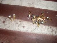
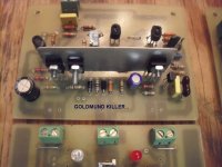
BTW , the "goldmund killer" (CX1.3) gets stuffed tommorrow AND lookie what I gotz .... (BELOW)
OS
Attachments
Nice. I haven't been feeling very smart the last few weeks and took a handful of vitamins yesterday. Better, but I still hate ordering parts online, especially when I have to do it from multiple vendors. But I think I'll be ready to order tomorrow...
- keantoken
- keantoken
Hi Os,
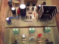
Could you take a look at this simulation?
It is quite simple amp and simulation shows 7ppm at 3kHz and 17ppm at 10kHz.
Third harmonic is a bit prominent but at -136dB I think it is not so important.
This is not bootstraped VAS because TT diodes need more stable current tnen bootstrap can provide.
dado
Attachments
what is 9ppm?
Hi,
9parts per million is 9/10^6 = 0.000009 = 0.0009%
I see 0.000009% as the simulated/predicted distortion on Ost 900 pic.
Hi,
9parts per million is 9/10^6 = 0.000009 = 0.0009%
I see 0.000009% as the simulated/predicted distortion on Ost 900 pic.
Hi Os,
Could you take a look at this simulation?
It is quite simple amp and simulation shows 7ppm at 3kHz and 17ppm at 10kHz.
Third harmonic is a bit prominent but at -136dB I think it is not so important.
This is not bootstraped VAS because TT diodes need more stable current tnen bootstrap can provide.
dado
Dadod , assume we have NONE of your models.My default models are gone, so include ALL models. I could not get to work without subbing for models I had. It works good...otherwise.
Think about it , at 120db or lower ... what is left to improve on ?? Input noise levels , thermal and Hfe matching , passive component choices , EVEN psycho acoustic considerations. As far as CCS vs. bootstrap , consider that TMC will correct the slight biasing inconsistencies that the t-traks are supposed to alleviate. YOU DON'T NEED THEM. The bootstrap , especially using a high quality Panasonic EE grade , will have a more "forward" bass response and still retain crystal clear detail at the high end...REALLY!
Use your $1.50 usd "run of the mill" 2sc5200/1943 , and still have class A Xover free operation. Also , feel free to add the cascode and experiment with FET or low noise BJT inputs.
OS
Hi,
9parts per million is 9/10^6 = 0.000009 = 0.0009%
I see 0.000009% as the simulated/predicted distortion on Ost 900 pic.
So what I have is .9 ppm ..WOW! I was basing from .1% not a full 1%
OS
What does this circuit look like into 3 Ohm load?
That would depend on your choice of OPS. Single pair , you might go "pooof" ... with my new 8 device NJW21193/4 PB250 , a whole different ballgame.
With my 8 device NJW0281/0302 board , testing with 2 pair 8R 15" 3-ways in parallel was standard (3R or lower). Never saw any VAS loading/heating , sound was the same at 20w or 200w.
The PB120 or your own 4 device output stage would be recommended for 6-8r loads medium duty. For 40C continuous operation (like I did with mine) into 3R
8 devices (Both the PB250 "N" and "H"). Very large heatsinks , too. (.1C/W) or better.
OS
I am only interested in max output of up to 40V peak to peak into 3R.
I don't go any louder than that. Actually 28V peak to peak is probably what I listen to most of the time (that is peak levels not average levels).
Generally speaking I always use at least two pairs, but it ends up being 3 pairs most of the time.
I don't go any louder than that. Actually 28V peak to peak is probably what I listen to most of the time (that is peak levels not average levels).
Generally speaking I always use at least two pairs, but it ends up being 3 pairs most of the time.
Last edited:
I am only interested in max output of up to 40V peak to peak into 3R.
I don't go any louder than that. Actually 28V peak to peak is probably what I listen to most of the time (that is peak levels not average levels).
Generally speaking I always use at least two pairs, but it ends up being 3 pairs most of the time.
With 3 pairs you might want to go the IRFP240/9240 route. My BX/CX ,etc. will run these as well , I just have not made the appropriate layout.
OS
ALL READY NOW... my "frankensteins" will LIVE.. ah haha
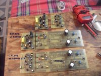
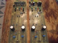
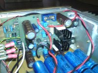
Finished the "goldmund killers" , much harder / more parts than the simple blameless's. I know they will not blow up , ampslab's bi240's (very similar) are proven. I know they are more stable and faster than the infantile goldmund designs . This is the 3' rd pair of "symasym" type voltage stages I've attempted , If these don't impress , I guess I'm a blameless man. I still have the "leech" (LX) to perfect/design/build ... so there is more to come. PHOTO's of perfect builds below !!!
OS
Attachments
Hi Os,
I did inlcude all models in the zip file, did'nt I?
By the way here is simulated distortion at 10kHz
Fourier components of V(vout)
DC component:-0.236072
Harmonic Frequency Fourier Normalized Phase Normalized
Number [Hz] Component Component [degree] Phase [deg]
1 1.000e+04 1.378e+01 1.000e+00 -0.91° 0.00°
2 2.000e+04 5.863e-07 4.255e-08 -50.57° -49.66°
3 3.000e+04 2.223e-06 1.613e-07 139.13° 140.05°
4 4.000e+04 1.913e-07 1.388e-08 34.14° 35.06°
5 5.000e+04 1.428e-07 1.036e-08 -43.06° -42.14°
6 6.000e+04 1.716e-07 1.246e-08 7.23° 8.15°
7 7.000e+04 3.496e-07 2.537e-08 -14.09° -13.17°
8 8.000e+04 2.032e-07 1.475e-08 -18.79° -17.87°
9 9.000e+04 2.242e-07 1.627e-08 -7.17° -6.26°
Total Harmonic Distortion: 0.000017%
At 3kHz it was 0.000003%
dado
Attachments
by the way, we should not call an amp with bootstraped VAS blameless, as D.S. used CCS in all his blameless creations.
dado
dado

Hello,
I like your thread even if I didn't have time to read it all...
Do you really intent to build all the various versions?
I like your thread even if I didn't have time to read it all...
Do you really intent to build all the various versions?
Member
Joined 2009
Paid Member


Hallo OS,
Maybe it’s better I go for the The MONGREL supersym II (OS and DX) than for the Goldmund.
When all is finished can I buy a completed module with all the parts on it?
Rudy
Maybe it’s better I go for the The MONGREL supersym II (OS and DX) than for the Goldmund.
When all is finished can I buy a completed module with all the parts on it?
Rudy
- Home
- Amplifiers
- Solid State
- The MONGREL (supersym II)