I have heard them at their home. I know the sim'd results are backed up by actual measurements by others.
I look forward to experiencing them in my home when they are available.
I look forward to experiencing them in my home when they are available.
Anyone have a recommendation for other devices than 2SC1845/2SA992 in section Q3-Q9 on the BX board? I cannot get 2SC1845/2SA992 with non of my local suppliers.
As i understand, for 2SA1381 i could use MJE350 with a slightly degree down on the performance?
As i understand, for 2SA1381 i could use MJE350 with a slightly degree down on the performance?
Anyone have a recommendation for other devices than 2SC1845/2SA992 in section Q3-Q9 on the BX board? I cannot get 2SC1845/2SA992 with non of my local suppliers.
As i understand, for 2SA1381 i could use MJE350 with a slightly degree down on the performance?
Reichelt and Schuro from Germany has them
i fear shipping price will be very high just for those components... if possible, i would rather like to use some i could get around here, from elfa or rs components f.ex...
OS
How many VA do I need for the PB250H per channel?
At least 300VA , I use a 1KVA for 2 channels , so 2 -400VA's would get you that sub 1V ripple at 200+ watts. My PS100 is 8200uF X 8 =65,600 uf + 6Kuf on the PB250's = 71,600 uf total. For dual mono , I would suggest 2- 400VA's 2- PS100's with up to 80Kuf for the most Kickarse medium sized amp setup.
Ksa992/sc1845 can be any ECB device with just a slight degradation (VERY slight) of performance. The ccs (2 X 2sc1845) can be any 120Vceo device (ECB) , I used 2sc2229 .. which is a black and white tv video amp device.. 😀 The input cascode is another low impact substitute ... it has NO gain , just a level shifter.
The 5 transistors that "count" are the 2 input devices , the current mirror and the beta enhancement device. These need to be high gain , low cob , and low noise. They even COULD be lower voltage except for the beta enhancement device. Using the MJE350 would be very good provided the beta enhancement device was "fast" , low Cob and high gain.
So , for those who sub (AX reference)
Q3-4 , 5-6 (cascode , CCS) can be any high voltage , medium performance device.( Hfe 100+ Vceo 100+ , BCE , NPN)
Q7 , 8 , 9 (current mirror , BE , PNP) 7 and 8 can be lower voltage , high gain , and should be loosely matched. Q9 is the major gain block for the whole amp , should be high voltage, high gain .
VAS devices can be any 200v+ to-126 device , (medium power Video driver) ,of which most to-126 devices are.
Q1-2 are the most important pair, they can be as low as 30Vceo but should be rated as "low noise audio amplifier" , have a gain of 400-800 with low Cob. These should be Hfe matched within 1 digit on a DMM.
OS
Thank you for the reply, ostripper.
I found a few with BCE/ECB pinout, not cheap ones actually, but they will work i believe. Before i order i would like a comment on them if they are a go or no go;
Q3, Q4, Q5, Q6 = 2SC1845 -> 2SC2240BL Vceo 120v, hFE 200-700
Q7, Q8, Q9 = 2SA992 -> 2SA970 Vceo 120v, hFE 200-700
Q10 = 2SA1381 -> MJE350
Datasheets:
https://www1.elfa.se/data1/wwwroot/assets/datasheets/07109143.pdf
https://www1.elfa.se/data1/wwwroot/assets/datasheets/07109135.pdf
And for Q1, Q2, i have following ones onhand;
BC549 measured hFE: 250-270
BC546 measured hFE: 198-205
MPSA42 measured hFE: 91-95
Should not be a problem to hfe match them to 1 digit, have lots of those.
Is it a go go?
What is the main differences in input boards?(GX,AX,BX). Im heading for BX, or should i use another one?
Thanks,
Stian
Yes , I forgot about the 2240/970 , they are real close to the 1845/992 ... nearly an ideal sub.
BC 549 , BCE .. I think the only issue would be the "back to back" , instead of the "face to face" .. position that is. I made a BX "BCxxx variant" but not an AX one. As long as the input pair is heatshrinked together , it won't matter much.
Mje340 is cool , as long as you use the 2sa970 as the beta enhancement ... no issue. Any offspec operation can be brought to spec by adjustment of "CCS adj."
You are good to go as I have used even worse offspec subs with glorious success. 🙂
OS
...
OS
Nice, thanks, will order the parts an give you an feedback when im done.
I will make a pair of leachamps, and a pair of PB250, and compare them against each other. Hunting for the optimal amps for a huge 7.1ch amp :=)
And that website off yours.... NICE, great its back online :=)
And for Q1, Q2, i have following ones onhand;
BC549 measured hFE: 250-270
BC546 measured hFE: 198-205
MPSA42 measured hFE: 91-95
none of your q1&2 proposals meet Ost spec.Q1-2 are the most important pair, they can be as low as 30Vceo but should be rated as "low noise audio amplifier" , have a gain of 400-800 with low Cob. These should be Hfe matched within 1 digit on a DMM.
This will increase input offset current which in turn will increase input offset voltage and lead to more drift in input offset voltage.
The overall result will be a higher and more variable output offset voltage.
Thats what i thought too..
What about BC547C? They are not rated as low noise audio amp, but have a typical hFE of 520. Vceo 45v.. or maybe BC550C? same hFE and Vceo, but is specified as a low noise amp..
Cob is typical 3.5pF
What about BC547C? They are not rated as low noise audio amp, but have a typical hFE of 520. Vceo 45v.. or maybe BC550C? same hFE and Vceo, but is specified as a low noise amp..
Cob is typical 3.5pF
Last edited:
I think that bc550c/560c will be more easily sourced.
There are many high voltage, high gain, low Cob, highish fT, low noise, 2sa/c transistors than can match and even better the performance of the cheap bc5x0c. There are also many reports that using these more expensive 2sa/c give improved sound quality.
You only need 4pairs for stereo. What about buying 10pair and matching them into amplifier pairs?
BUT,
the pin outs are different !
About output stage
Well, it looks like you have designed a superb (set of) amplifier!
I have (randomly) followed the development and have seen that no much compromises were taken in the research of very low THD and noise.
My sincere compliments for the succesful outcome!
Particularly I like the modular design, that really gives you more degrees of freedom (as a designer, but also as a DIY builder) when a project start to be a little more complex, like this.
Now, maybe I have missed it, but did you investigate some alternative topology for the Output ? According to some relevant theories , CFP, while more tricky to stabilize, offers better Xover distortion (I know, overall you have almost nothing, but, what about when the voulme is set to 10%?). I 'll love to see how you would implement a double or quad pair output like PB120 or PB250, in particular. I believe it might be worthy to research a little on this topic, if nothing else.
bye
effebi
Last edited:
Well, it looks like you have designed a superb (set of) amplifier!
I have (randomly) followed the development and have seen that no much compromises were taken in the research of very low THD and noise.
My sincere compliments for the succesful outcome!
Particularly I like the modular design, that really gives you more degrees of freedom (as a designer, but also as a DIY builder) when a project start to be a little more complex, like this.
Now, maybe I have missed it, but did you investigate some alternative topology for the Output ? According to some relevant theories , CFP, while more tricky to stabilize, offers better Xover distortion (I know, overall you have almost nothing, but, what about when the voulme is set to 10%?). I 'll love to see how you would implement a double or quad pair output like PB120 or PB250, in particular. I believe it might be worthy to research a little on this topic, if nothing else.
bye
effebi
Thanks for kind words... hey , why you pick on the lowly EF2 ?? 😀 A nice triple EF has been made , but I will only finalize it for a 4R sub amp.
Volume set to 10% ??? I have set my volume to 50% and could barely see X-over distortion on the CRO. My next "adventure" will be MOSFET drivers and lateral output stages. (PBM120/250)
The CLX is next for voltage stage development. (next to be actually made and tested ,that is) 🙂
OS
Ops, sorry, I do not want to criticize your EF2😀😀😀 . It's lovely done, it has base stoppers even on the driver (if I remeber well) and nice so-called linear regulators to supply back the low power stages. I was just wondering why not, after pursuing distorsion everywhere else, to try do it on the Output whre it can still show up al little. I believe (just an impression) that I would show a LITTLE bit more at low volume settings where the EF transistors work more in the transition zone. And for what reminds to me, in this case CFP would show some nicer behavior (at the cost of stability risk). I have seen very few (maybe only in a Crown, not sure) double CFP2 (i.e. One driver and two Finals for each polarity) and I was just curius to see one's perfectionst implementation. BTWI do not like EF3 or CFP3 stages for such power, seems unnecessary nowadays .Thanks for kind words... hey , why you pick on the lowly EF2 ?? 😀 A nice triple EF has been made , but I will only finalize it for a 4R sub amp.
Volume set to 10% ??? I have set my volume to 50% and could barely see X-over distortion on the CRO. My next "adventure" will be MOSFET drivers and lateral output stages. (PBM120/250)
The CLX is next for voltage stage development. (next to be actually made and tested ,that is) 🙂
OS
bye
effebi
1. I believe (just an impression) that I would show a LITTLE bit more at low volume settings where the EF transistors work more in the transition zone. And for what reminds to me, in this case CFP would show some nicer behavior (at the cost of stability risk).
2. BTWI do not like EF3 or CFP3 stages for such power, seems unnecessary nowadays .
bye
effebi
Two good discussions regarding "choices". 🙂
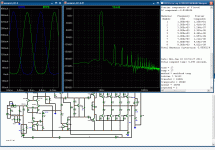
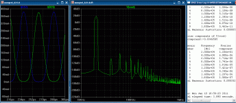
# 1 . At very low volumes (pix 1-2) we are technically in class A , none of the outputs ever go below 5ma (never shut off). So this means the AX/PB250's "first watt" is pure class A up to about 10 watts/8R. No TMC signal is being fed back to Cdom , so this is the true performance of this amp "raw" . VERY impressive at 1k !!!
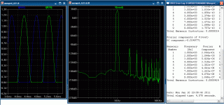
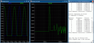
At 100W (pix 3-4) , my conservative implementation of TMC keeps the Xover distortion under wraps , increasing from .1ppm to a whole .4ppm(1K) , at 20 Khz it goes from 3 to 8 ppm , still quite acceptable.
#2 This is a choice of application , X-over THD get far worse at 4R and below , even with a greater "dose" of TMC. This can be negated to a point by using a triple EF OP and lowering the damping factor. The damping factor (or lack of) is what "sours the TMC milk" being fed back to the VAS. It is also of great concern that the slight gain of a CFP stage would destabilize TMC by creating to many poles in the OPS ( FF CFP loop surrounded by the TMC loop). I might not implement TMC on my EF triple as it will just be a sub amp anyway.
PS . the un- TMC'ed BX has about the same SPECS at low levels , but is slightly "bettered" by the AX at high output.


OS
Attachments
I have 3 questions ....
1- On the '' PB120N '' power board the resistor at the collector of Q93 ( Vbe multiplier ) is named '' RSELF '' and I dont know the reason for this special name ??
2- The red led current is 3 times the current of the blue one, does the blue led have a very high efficiency ?
3- On the '' AX 1.3 VB '' input circuit there is a note about '' TMC '' and a possible modification around the feedback and '' Cdom '' I dont know the expression
And one comment on the PB120N ..... I found no output transistor protection circuit ..
I have 3 questions ....
1- On the '' PB120N '' power board the resistor at the collector of Q93 ( Vbe multiplier ) is named '' RSELF '' and I dont know the reason for this special name ??
2- The red led current is 3 times the current of the blue one, does the blue led have a very high efficiency ?
3- On the '' AX 1.3 VB '' input circuit there is a note about '' TMC '' and a possible modification around the feedback and '' Cdom '' I dont know the expression
And one comment on the PB120N ..... I found no output transistor protection circuit ..
#1.That is self's "magic resistor" at a value of 10-16R , it reduces the current variations across the Vbe device. it is optional and can be jumpered.
#2 - the safety LED's , yes the typical blue has over 3 times the output lumen wise than the typical red. If you use a high brightness red , you might have to use 33k to reduce it's brightness (unless you like it bright 😀 )
#3 - On the AX , you can run either "flavor" of Cdom= (capacitor which sets the dominant frequency pole of the amplifier). In the single 47pf "mode" (traditional) there is one pole set by the cap. in the TMC "mode" there are 2 poles , each of which has it's own frequency. when I designed the amp , TMC was still in "R & D" ... now I use this amp daily and it is "bugfree".
Hope this demystifies the material .. 🙂
OS
- Home
- Amplifiers
- Solid State
- The MONGREL (supersym II)


