I found that I got a few mA of plate current with no B+ or grid voltage when the filament of the 833A was lit. 100 watts of heater power will send a few electrons streaming toward the plate. I got some audible hum in the speaker with only heater power turned on. I was using raw AC from a big transformer. Moving the heater and OPT's around on the bench did not affect the hum, but disconnecting the plate lead killed it.
Yes, I read this on your site. I'll try disconnecting the plate lead tonight and see if the noise goes away. I'm using Rod Coleman's DC filament boards, so I don't expect much noise to be on the filament supply, but it doesn't hurt to check. Thanks for the idea.
Honestly, I'm happily surprised by how low the total noise is already, considering what's in the box.
I assembled a 304TL amp years ago and I ended up moving the filament supplies to a different chassis for this very reason. This facilitated also moving the amp around.
So you had noise at this level or was it higher? I don't think I'll go to two boxes when my noise is already so low, but a little shielding here and there might be in the cards.
Honestly, I'm happily surprised by how low the total noise is already, considering what's in the box.
Yes, you have done an amazing job of getting 12 pounds of stuff into a 5 pound box. Maybe it's just time to sit back and enjoy the mono for a while while making #2.
I have come to realize that if it sounds good, maybe it's time to leave it alone rather than risk making it worse or breaking something.
It is 4 boxes actually! I can't remeber any number but it was too hot and noise was annoying. When I rebuilt it noise was drammatically reduced and was barely heard thorough my 416A onkens.
Shielding with mu metal foils did not improve things that much hence the decision to rebuild the monster. In my case there were high inductance input trans and signal chokes picking up noise regardless of the orientation
Shielding with mu metal foils did not improve things that much hence the decision to rebuild the monster. In my case there were high inductance input trans and signal chokes picking up noise regardless of the orientation
It is 4 boxes actually! I can't remeber any number but it was too hot and noise was annoying. When I rebuilt it noise was drammatically reduced and was barely heard thorough my 416A onkens.
Shielding with mu metal foils did not improve things that much hence the decision to rebuild the monster. In my case there were high inductance input trans and signal chokes picking up noise regardless of the orientation
Hi Gluca,
Did you use AC or DC heating on your 304TL?
I'm planning to build an 304TH SET and filament heating is gonna be a pita.
Duong
DC. It was cLCL filtered, chokes were double bobbins. It was before Rod's regulators.
304 is really a beast, transformers were sweating because of the heat it was dissipating; i rewired the amp for 75TLs to cool things down
Lovely tubes!
304 is really a beast, transformers were sweating because of the heat it was dissipating; i rewired the amp for 75TLs to cool things down
Lovely tubes!
DC. It was cLCL filtered, chokes were double bobbins. It was before Rod's regulators.
304 is really a beast, transformers were sweating because of the heat it was dissipating; i rewired the amp for 75TLs to cool things down
Lovely tubes!
By the way did you use 10V heating or 2x5V?
Since the 304TH/L has 2 x5V filaments, I hope heating them separately in opposite directions might help.
Yes, you have done an amazing job of getting 12 pounds of stuff into a 5 pound box. Maybe it's just time to sit back and enjoy the mono for a while while making #2.
🙂
I have come to realize that if it sounds good, maybe it's time to leave it alone rather than risk making it worse or breaking something.
Now there's an idea. I strongly agree. Don't mod yourself to death. Enjoy your amp.
~Tom
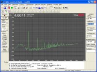
Thought you might be interested in the noise floor measurement for the Midlife Crisis.
Not bad for a one chassis amp with a 10A filament supply, a 450V driver supply, a 2300V 833 supply and a fan all in one box. I'm pleased!
As a sanity check, it is also dead quiet on 89dB speakers.
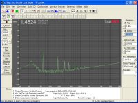
300 uV on the output is very nice indeed. I generally aim for below 1 mV - preferably well below - for my 87~90 dB efficient speakers.
As you point out, 60, 120, 180 ... Hz (mains harmonics) are the main contributors to the "noise". Unless you shield with mu metal, shielding is not likely to help you. The skin depth at 60 Hz in copper is on the order of 5 mm, so good luck with your shielding... 🙂
What you could do is to measure the ripple+noise on the B+ supply and the amp output with a voltmeter. I bet you'll find that the ratio between these voltages is rather close to the turns ratio of your OPT. This would imply that the residual ripple you have on the output is ripple from the B+ supply through the OPT. The only ways to get rid of that would be better B+ filtering or B+ regulation (good luck).
On the other hand, if the ripple leaks through a bias supply, a cap in the right place may be all that's needed to lower the hum.
But, honestly... It doesn't look like you have a problem, so don't fix it.
~Tom
I have come to realize that that last db or two are the hardest to get, and in their quest the opportunity to screw up are at their greatest.
This discussion came to a head in my wood shop class last night. The difference between wood and circuits are found in how far you have to back up to get where you were before you screwed it up.
You might fry a few parts trying to make 96 watts into 100 just because 100 sounds much bigger than 100, but there is no audible difference. replace the toasted parts and try again.
I "quit while I was ahead" while working on a guitar body last night, which prompted a discussion that was started by a class member who wasn't present when I threw the last guitar body in the trash after I "tried to make it better" and screwed it up.
300 uV on the output is very nice indeed. I generally aim for below 1 mV - preferably well below - for my 87~90 dB efficient speakers.
~Tom
Thanks, Tom. My main speakers (Infinity RSIIb) are on the order of 85dB efficient (if that), so I have even less to worry about.
As you point out, 60, 120, 180 ... Hz (mains harmonics) are the main contributors to the "noise". Unless you shield with mu metal, shielding is not likely to help you. The skin depth at 60 Hz in copper is on the order of 5 mm, so good luck with your shielding... 🙂
~Tom
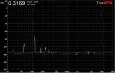
I use TI-Shield when I do shielding. It's a composite with a core of soft iron for magnetic fields, coated on both sides with copper for electrostatic fields. It is effective, for sure, I've used it to filter out mains frequencies in other projects, getting about a 10dB attenuation at 60Hz, and significant attenuation at higher frequencies as well, for a single sheet grounded to the chassis. Best part is, you can bend it and solder it without affecting its shielding properties, unlike mu-metal.
Below are before and after measurements on an equalizer I modified by shielding the power supply.
.
Attachments
Last edited:
This would imply that the residual ripple you have on the output is ripple from the B+ supply through the OPT.
~Tom
I don't think so, as I said, I can see the same peaks at 120, 180, 240, etc. with the 833 B+ completely off, only the filament supply and driver supply on. When it's all turned on there are additional peaks added, but the mains ripple peaks stay pretty much the same.
OK, so just to satisfy my curiosity, I did a few experiments.
1) Measured the noise with only the filament and driver circuits on, 833 B+ off (picture 1).
2) Repeated #1 with plate cap disconnected - no change.
3) Placed piece of TI-Shield between filament transformer and outputs, no improvement.
4) Placed piece of TI-Shield between filament chokes and outputs, no improvement.
5) Placed piece of TI-Shield between filament and driver circuits, no improvement.
6) Placed piece of TI-Shield between filament and 833 B+ circuit, no improvement.
Screwed bottom back on amp, turned it upright, and resolved that it was Good Enough!
I think I've just reached the limit of quietness for such an assemblage of parts, and that's plenty good enough. Time to move on to amp #2.
Attachments
TI plate? Please elaborate... Do you have a link to a vendor who carries it?
You talk about a composite structure so I'm guessing TI ≠ Titanium.
~Tom
You talk about a composite structure so I'm guessing TI ≠ Titanium.
~Tom
Hi Bob, Looks like good results.
As noted, the most likely source for the remaining spectrum is direct-coupling of magnetic field from the Filament supply transformer/choke to signal-parts or wiring.
Now that you have resolved to build the second channel, there's one test that could confirm the source:
- build the second filament raw dc supply, as before.
- Stand this new supply 1 metre or more from the amp, and connect to the filament regulators, in place of the raw supply built into the chassis.
- Take the spectrum again, and compare.
BTW, for the Eimac 75TLs Gianluca mentioned: the filaments for these can be fed from one of my 6.25A Filament regulators, with temperature-compensation.
TI plate? Please elaborate... Do you have a link to a vendor who carries it?
You talk about a composite structure so I'm guessing TI ≠ Titanium.
~Tom
TI stands for Texas Instruments, who developed the material, a sandwich of copper/alloy49/copper. I purchased it from Michael Percy Audio (link, page 14 of catalog), but I notice it now says on their site it's "not currently in production".
http://www.percyaudio.com/Catalog.pdf
Hi Bob, Looks like good results.
As noted, the most likely source for the remaining spectrum is direct-coupling of magnetic field from the Filament supply transformer/choke to signal-parts or wiring.
Thanks, Rod.
The magnetic field emanating from the filament transformer and chokes is very powerful, with 10A of current going through them they're basically electromagnets! When I moved the TI-Shield near the chokes the field pulled the shield right up against the choke, like a speaker magnet would. Frankly I'm surprised the circuit effect is as small as it is, given that fact. I'm not worried about microvolts of noise for this application, it's plenty quiet as is.
- Home
- Amplifiers
- Tubes / Valves
- The Midlife Crisis - My 833C Amp Build