As far as stiffing up the box, has anyone thought of using threaded bars/bolts that span between opposite baffles and can be tightened from the outside? I expect tension would reduce vibration. The tension could be adjusted at any time.
dzzmiller said:As far as stiffing up the box, has anyone thought of using threaded bars/bolts that span between opposite baffles and can be tightened from the outside?
Yes. The idea comes up every once in a while. It works. You have to make sure the rod doesn't ring.
dave
It would be interesting to build a column type box with tie rods. Then test the box with and without tension. Although I think the metronome is a design, with its small volume and long sides, that probably wouldn't benefit.
I expect some builds would benefit from thicker side walls. For a home or local builder it wouldn't be much of a cost increase. Although it would push some designs into a weight class that couldn't be handled by one person.
I expect some builds would benefit from thicker side walls. For a home or local builder it wouldn't be much of a cost increase. Although it would push some designs into a weight class that couldn't be handled by one person.
I'm curious how you guys made your driver choice? I'm thinking about the Jordan, but I really don't know which to use.
mostlyrandom said:I decided a few weeks ago to build a pair of metronomes. Thanks to Dave at Planet 6 who provided the awesome drivers.
well, we're all aware of the current economic situation, but that's still Planet 10 😀
adjustable rods
peter
Indeed, this can work quite well. It's an exercise in getting the resonant frequency out of the way. This in turn is a function of areas and stiffnesses, etc. It may be enlightening to look at this patent: http://www.google.com/patents?id=U9Z_AAAAEBAJ&dq=marcel+gavriliudzzmiller said:As far as stiffing up the box, has anyone thought of using threaded bars/bolts that span between opposite baffles and can be tightened from the outside? I expect tension would reduce vibration. The tension could be adjusted at any time.
peter
Re: adjustable rods
That he got a patent for that shows again the holes in the patent office... doing things like this goes back before this guy was born.
dave
schro20 said:It may be enlightening to look at this patent:
That he got a patent for that shows again the holes in the patent office... doing things like this goes back before this guy was born.
dave
adjustable rods
In general I certainly agree with your point.
peter
Yeaaah. FWIW, I am not endorsing this or any other approach. Ironically though I have found it useful to see what others (companies in particular) do by looking at patents (and doing appropriate amounts of reading between the lines). For research purposes it's all fun and perfectly usable.planet10 said:That he got a patent for that shows again the holes in the patent office... doing things like this goes back before this guy was born.
In general I certainly agree with your point.
peter
If you think that's bad, I advise taking a gander at US Patents Nos 6,486,750, and 6,025,810, if you enjoy a good laugh.
Well, at least the good thing is that we won't have to defend our own designs as being in violation of a patent for faster than light transport... 😉Scottmoose said:If you think that's bad, I advise taking a gander at US Patents Nos 6,486,750, and 6,025,810, if you enjoy a good laugh.
If only these geniuses could figure out a way to get rid of the pesky effects of the laws of physics when it comes to sound reproduction...
peter
Re: adjustable rods
Well O.K. I just can't keep up with those brillant academics. Seriously, it seems to me that an easy way to add tension or compression to the wood is useful. I wonder sometimes how extensive wood bracing effects the sound by directly interacting with the waveforms.
I would still like to know the criteria you guys used to pick a specific driver for the metronome.
I see Jordan has a new 2 inch drive. That speaker could be fit into a real metronome.
schro20 said:
It may be enlightening to look at this patent: http://www.google.com/patents?id=U9Z_AAAAEBAJ&dq=marcel+gavriliu
peter
Well O.K. I just can't keep up with those brillant academics. Seriously, it seems to me that an easy way to add tension or compression to the wood is useful. I wonder sometimes how extensive wood bracing effects the sound by directly interacting with the waveforms.
I would still like to know the criteria you guys used to pick a specific driver for the metronome.
I see Jordan has a new 2 inch drive. That speaker could be fit into a real metronome.
Re: Re: adjustable rods
Well, it's not like Einsteins work at the patent office.
planet10 said:
That he got a patent for that shows again the holes in the patent office... doing things like this goes back before this guy was born.
dave
Well, it's not like Einsteins work at the patent office.
Did you follow the link to 5,731,554? Seems that Sony has patented t-nuts and baffle gaskets for driver mounting.
Bob
Bob
Bob Brines said:Did you follow the link to 5,731,554? Seems that Sony has patented t-nuts and baffle gaskets for driver mounting.
Bob
has anyone applied for patent on thermo-set aliphatic resin post veneering process?

Last summer I decided I wanted to see if there is magic in Alnico drivers. I’m not quite ready to pony up the coin for Lowthers, so I bought a pair of Fostex F120A. I had thought to beg Scottmoose to calculate a Metronome cabinet for the F120A, but Martin encouraged me to have a go at it myself. And thus begins the tale...
The models I calculated seemed much less sensitive to small dimensional changes than I had expected. I am uncertain that I have found the best solution, but here is what I decided to build. Dimensions are for the internal volume, in the format used in the Metronome tables on the Frugelhorn site.
L= 52 inches
Z(driver)= 22 inches
S(0)= 2.5 x 2 inches
S(L)= 9.5 x 5.25 inches
Port Diameter = 3 inches
Port L = 4 inches
About three weeks ago as the weather warmed, I moved my wife’s car out of the garage, moved my tools back in, and began to cut wood (at my usual glacial pace.) At this point, I have produced the fronts, backs, and sides for the F120a Mets. Since those cuts aren’t square, they can’t be done easily on a table saw. What I did was to rough cut the parts slightly over-sized using the circular saw free hand; then I used a metal guide and the router with a flush trim bit to obtain the correct size with a nice, clean straight edge. I used the first piece as a pattern to cut the others w/ the flush trim bit. I found this a much better method than my previous FE108eS Met build where I cut the parts with a jig saw and a guide.
Having purchased the drivers last year, I had enough cash on hand to buy a few clamps. Screws are a thing of the past, and I am pushing ahead with dowel pins and clamps.
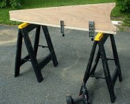
And as to dowel pins: I don’t have a drill press, so I tried to build a jig to drill the holes. After spending a day getting 7 sets of holes ready for dowels, and not being happy with the result, I conceded defeat and went down to Sears, credit card in hand, to buy a proper set of clamps and jigs. See photo below.
When the dowel pin holes are all ready, I expect to begin applying finish to the exterior surfaces. That way, the excess glue can’t cause problems with the finish. Interior surfaces will have polyurethane applied before ‘close-up.’ I firmly believe in having ALL surfaces finished/sealed.
to be continued....
The models I calculated seemed much less sensitive to small dimensional changes than I had expected. I am uncertain that I have found the best solution, but here is what I decided to build. Dimensions are for the internal volume, in the format used in the Metronome tables on the Frugelhorn site.
L= 52 inches
Z(driver)= 22 inches
S(0)= 2.5 x 2 inches
S(L)= 9.5 x 5.25 inches
Port Diameter = 3 inches
Port L = 4 inches
About three weeks ago as the weather warmed, I moved my wife’s car out of the garage, moved my tools back in, and began to cut wood (at my usual glacial pace.) At this point, I have produced the fronts, backs, and sides for the F120a Mets. Since those cuts aren’t square, they can’t be done easily on a table saw. What I did was to rough cut the parts slightly over-sized using the circular saw free hand; then I used a metal guide and the router with a flush trim bit to obtain the correct size with a nice, clean straight edge. I used the first piece as a pattern to cut the others w/ the flush trim bit. I found this a much better method than my previous FE108eS Met build where I cut the parts with a jig saw and a guide.
Having purchased the drivers last year, I had enough cash on hand to buy a few clamps. Screws are a thing of the past, and I am pushing ahead with dowel pins and clamps.
And as to dowel pins: I don’t have a drill press, so I tried to build a jig to drill the holes. After spending a day getting 7 sets of holes ready for dowels, and not being happy with the result, I conceded defeat and went down to Sears, credit card in hand, to buy a proper set of clamps and jigs. See photo below.
When the dowel pin holes are all ready, I expect to begin applying finish to the exterior surfaces. That way, the excess glue can’t cause problems with the finish. Interior surfaces will have polyurethane applied before ‘close-up.’ I firmly believe in having ALL surfaces finished/sealed.
to be continued....
Attachments
Jim Shearer said:About three weeks ago as the weather warmed, I moved my wife’s car out of the garage, moved my tools back in, and began to cut wood (at my usual glacial pace.)
If you define your pace as "glacial", I have to wonder if my pace even has a pulse. I hope that over the next couple of months we can have some more listening sessions, we will both have new designs to discuss.
Jim Shearer said:
...Since those cuts aren’t square, they can’t be done easily on a table saw. What I did was to rough cut the parts slightly over-sized using the circular saw free hand; then I used a metal guide and the router with a flush trim bit to obtain the correct size with a nice, clean straight edge.
Have you considered making a sawboard?
And as to dowel pins: I don’t have a drill press, so I tried to build a jig to drill the holes. After spending a day getting 7 sets of holes ready for dowels, and not being happy with the result, I conceded defeat and went down to Sears, credit card in hand, to buy a proper set of clamps and jigs.
I have found using a biscuit joiner when constructing speakers significantly simplifies the glue up process because you can dry fit in advance and if you set it up right, all seams come together perfectly.
I highly recommend these two tools.
- Home
- Loudspeakers
- Full Range
- The Metronome