I have been giving these a listen the last few days. Initial impressions weren't good. By this I mean I guess I was just expecting more and first off thought man those fe127e's in the fonken floorstander were really doing a great job.
First impressions started without the rear panel glued (clamped) to do the dampening thing to taste. Noticed there was allot of resonance going on with the encloser so I got the dampening close enough then glued them up that night.
Next test they were finished and glued, stiil nothing special less resonance althought it was still present (acceptable). You could tell they were going lower, not much, than the fe127e's but the magic wasn't there 😕 This was the case that was going on till I applied the war paint to the fe127e's so I figured this needs to be done soon minus the damar.
Today at work I got thinking (I know that's scary) and I knew this going in that these are being used on carpet so this evening I placed some ceramic tiles underneath them. What a differance this made, they just opened up 😀. Didn't think this would have made that much differance since I didn't feel allot of pressure coming out of the port. What a relief this was, looking forward to these getting nothing but better now.
The fostex shout is there so precoat to the enable will be next along with Dave's phase plugs then I will have another look at the dampening. Oh yeah, can't forget the bandaid that was discussed a couple of post up.
To get back to the resonance. You can definitely tell that the top of the enclosure especially the top cap is where it's at. This makes sense since I think the wave form goes up before it exits to the port. Hope that was right in layman's terms. What do yall think about if building this again about extending the driver brace higher and making the top cap 1.5" thick in the future?
Thanks Steve for being the first to try these out and to Dave, Scott and Steve for the dedication to get them right. What would we do without yall, thanks again.
ecir38 said:Today at work I got thinking (I know that's scary) and I knew this going in that these are being used on carpet so this evening I placed some ceramic tiles underneath them. What a difference this made, they just opened up 😀. Didn't think this would have made that much difference since I didn't feel al lot of pressure coming out of the port. What a relief this was, looking forward to these getting nothing but better now.
Yes, it is surprising, the improvement that can be gained by placing a solid surface underneath the port. The sound gets bigger and hangs free of the speakers. The solid surface below the port trick was first suggested, in an email by a guy from Canada. Can't remember who now as it was at least two years ago.
He too had built some FE207 Metronomes. Placed on carpet they were bass light and closed in. He put a pair of teak chopping boards under his, if I remember rightly and reported a phenomenal improvement in the overall presentation.
Those builders who have placed their Metronomes on solid floors have reported no problems with their speakers, yet builders with carpet floors almost always report bass lightness and lifelessness, so something is definitely going on at the port/floor interface despite the low pressure at the port mouth.
I wonder if a bit of a redesign at the port/floor boundary might negate this problem ie a built in solid base to the enclosures.
Steve
ecir38:
To reduce the resonances, you could try some additional mass on the top, such as Corian or granite offcuts from a counter-top shop, and/or externally cladding the back side of the enclosure with thin layers of materials of different densities - i.e. MDF / cement board above the driver, and plywood below
To reduce the resonances, you could try some additional mass on the top, such as Corian or granite offcuts from a counter-top shop, and/or externally cladding the back side of the enclosure with thin layers of materials of different densities - i.e. MDF / cement board above the driver, and plywood below
Steve Cresswell said:I wonder if a bit of a redesign at the port/floor boundary might negate this problem ie a built in solid base to the enclosures.
Steve
I knew these were going on carpet and should had cut some bases out during the build. Don't think a redisign is needed as long as it is documented that somethig is needed if placing on carpet. The tiles I have now are just temporary, I am going to cut some black ones to fit in between the legs and just lay them under the enclosure to see how that works out.
chrisb said:To reduce the resonances, you could try some additional mass on the top, such as Corian or granite offcuts from a counter-top shop, and/or externally cladding the back side of the enclosure with thin layers of materials of different densities - i.e. MDF / cement board above the driver, and plywood below
It really isn't that bad now that the enclosures are glued, but if I did build another pair I would probably do what I recommended above. Steve, do you notice anything like this with the smaller enclosure, maybe it is just noticable on the larger mets.
BR
ecir38 said:
I knew these were going on carpet and should had cut some bases out during the build. Don't think a redisign is needed as long as it is documented that somethig is needed if placing on carpet. The tiles I have now are just temporary, I am going to cut some black ones to fit in between the legs and just lay them under the enclosure to see how that works out.
It really isn't that bad now that the enclosures are glued, but if I did build another pair I would probably do what I recommended above. Steve, do you notice anything like this with the smaller enclosure, maybe it is just noticable on the larger mets.
BR
Brad / Scott, it seems logical to me that as you step up to the larger drivers, the panel dimensions will of course increase and their natural resonant frequencies decrease.
Furthermore, the amplitude of energy inside the cabinet will be much higher with an 8" and a 4", would require strategic bracing and selective panel mass loading / damping to distribute / dissipate this energy. Bolting the enclosure to a granite concrete paver stone or even steel plate mass load might also help sink some of the panel's kinetic energy to the floor.
![met207-aux-brace-placement[1].jpg](/community/data/attachments/102/102472-51bcc53ea5b9228561b4b11f6d0e7762.jpg?hash=UbzFPqW5Io)
ecir38 said:Maybe adding a couple of braces like the one I made for access to the bottom glued above the driver instead of making the driver support longer would be better.
I thought you said the enclosure was fully glued up? If you're still able to access the entire inside, then a few off-center, vertically oriented ribs, and another couple of cross braces could help couple the 4 main panels together, and significantly stiffen the entire enclosure, as well as distribute the resonant energy into a broader spectrum.
Rather than window-pane brace such as at the bottom, I'd suggest pairs of 3/4" x 3" vertical cross braces connecting oppose side panels, interlocking in an X-pattern. I'd also try to cross brace the driver brace to the side panels, below the driver.
Without invoking the "ultra-mass/stone cold dead vs musically consonant" debate, I'll note that based on experience with building identical enclosures from different materials, it is possible to over-damp an speaker cabinet, so careful incremental experiment and listening will be your best approach.
I've not actually built a pair of these, but based on what I've read by several others on experience with resonant pipes or MLTL, some mass load at the top of the enclosure could be beneficial in disturbing the node at the focused end of this tapered design. Has anyone experimented with pouring a couple of inches of cement or shot filled epoxy resin in the tip of the 'nomes?
They are glued, if you haven't noticed that was earlier pic from a few post up and at the end of the previous page. Like I said earlier now that they are glued I don't think this is of major concern and maybe some additional bracing would be needed above the driver. Below the driver is alright since I don't think much is going on there anyway.
BR
BR
Came back in town today and the phase plugs were here 😀 Thanks for the quick response and shipping Dave.
BR
BR
Actually the kid said they came in on Friday or Saturday which was less than a week. I have never received anything this fast from Canada before.
BR
BR
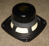
Pulled the driver's out last night to do the precoat to enabel. One coat last night and the other tonight. Enable will come at a later date when I get my nerve up to do them. I went ahead and glued the braces like Dave recommended for the driver brace too.
The other thing on the list was to do some basket mods. It isn't as dramatic as what Dave is doing here http://www.diyaudio.com/forums/showthread.php?postid=1649080#post1649080 but can tell this is going to help by the differance between the ping of the finished and not finished driver when tapping on them. See pic below.
I installed the phase plugs last week. The best way I can described it is they are doing better in the upper mid's and high's like the fe127e's did so well in my fonken floorstander.
BR
Attachments
Using 127e Metronomes with an F2
I built my 127e Metronomes about six months ago. I have been using them with DIY Aleph 30 monoblocks and am in the process of finishing up an F2 to replace them. This has led to a question on BSC implementation for current source amplifiers. I am currently using a 4 db BSC and would like to start my adjustments using the same values.
As the standard BSC requires a paralleled inductor and a resister placed in series with the 127e, I am assuming that the equivalent current source circuit would be the inductor and resister placed in series and paralleled with the 127e. Is this correct?
I also assume that a zobel shouldn’t be required for current source amplifiers? I didn't see any reference to using them in Nelson Pass's article on using current source amplifiers with full-range drivers.
Has anyone tried a F1/F2 with 127e Metronomes? If so, what size resister did you end up across the output?
BSC circuit for 207e Mets
Basically I want to experiment with a BSC circuit, but let me first say where I am at right now before asking my question (HOW to experiment?).
After experimenting with different stuffing and listening and measuring I finally glued mine shut. They now have acoustic foam in the top section (starting from bottom part of driver to top of cavity) on 3 walls. It sounded and measured the same as acousta stuffing and seemed less hassle.
I tried them on different amps. First a tube amp (Onix Sp3). Nice but too soft (flabby?) in the bass for my taste. Then, big surprise, a little Sonic Impact 2. Wow! Not very loud because you can only get so many good watts out of that little thing, but for normal listening just fine. And SO MUCH more authority in the bass. Quite a difference. Still experimenting with different amps (building a revC right now). Right now just running them off an Onkyo in the bedroom.
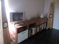
Tonal balance? Well, it still needs work. But I am having a really tough time just even finding the right words for describing what ails them to my ears. The bass is strong and moves some real air (they are sitting on a naked hardwood floor and are close to the wall). But somehow in the mid range they sag, or are unclear. I am wondering whether I am simply noticing that they are missing sparkle at the top. My main system is a set of Linkwitz Plutos which have far more sparkle(?). Crystal clarity(?). Something like that. This may require bringing in a tweeter (something I have noticed people recommending repeatedly for the 207e...).
But before I do that I want to play with BSC a bit to understand that better and see what it might do for me (I understand the physics for BS and BSC). I looked at the Metronome table which gives values for BSC and Zobel for the 207e. I don't really see the need to have a Zobel for my setup, so I am planning on skipping that. But then I wonder whether the values suggested for the BSC are independent of the values for the Zobel. Are they?
Can someone give me some intuition behind the parallel L and R? (I can work out the impedance of the parallel R and L... but that doesn't help with understanding this qualitatively...) My usual approach to such a problem would be to get, say, 3 different examples to get some sense of the contrast. Something that's probably about right, something that goes way in one direction, something that goes way in another direction. Then I can often judge which direction I want to head in (parameterwise) to fine tune.
Can someone suggest a few values to try that might help me explore this parameter space? Or suggest a different approach that will help me understand the range of things I can hope for with this?
Thanks much!
peter
PS: some development pictures and beauty shots at http://picasaweb.google.com/schro20/MetronomeFE207eBuild?feat=directlink
Basically I want to experiment with a BSC circuit, but let me first say where I am at right now before asking my question (HOW to experiment?).
After experimenting with different stuffing and listening and measuring I finally glued mine shut. They now have acoustic foam in the top section (starting from bottom part of driver to top of cavity) on 3 walls. It sounded and measured the same as acousta stuffing and seemed less hassle.
I tried them on different amps. First a tube amp (Onix Sp3). Nice but too soft (flabby?) in the bass for my taste. Then, big surprise, a little Sonic Impact 2. Wow! Not very loud because you can only get so many good watts out of that little thing, but for normal listening just fine. And SO MUCH more authority in the bass. Quite a difference. Still experimenting with different amps (building a revC right now). Right now just running them off an Onkyo in the bedroom.
Tonal balance? Well, it still needs work. But I am having a really tough time just even finding the right words for describing what ails them to my ears. The bass is strong and moves some real air (they are sitting on a naked hardwood floor and are close to the wall). But somehow in the mid range they sag, or are unclear. I am wondering whether I am simply noticing that they are missing sparkle at the top. My main system is a set of Linkwitz Plutos which have far more sparkle(?). Crystal clarity(?). Something like that. This may require bringing in a tweeter (something I have noticed people recommending repeatedly for the 207e...).
But before I do that I want to play with BSC a bit to understand that better and see what it might do for me (I understand the physics for BS and BSC). I looked at the Metronome table which gives values for BSC and Zobel for the 207e. I don't really see the need to have a Zobel for my setup, so I am planning on skipping that. But then I wonder whether the values suggested for the BSC are independent of the values for the Zobel. Are they?
Can someone give me some intuition behind the parallel L and R? (I can work out the impedance of the parallel R and L... but that doesn't help with understanding this qualitatively...) My usual approach to such a problem would be to get, say, 3 different examples to get some sense of the contrast. Something that's probably about right, something that goes way in one direction, something that goes way in another direction. Then I can often judge which direction I want to head in (parameterwise) to fine tune.
Can someone suggest a few values to try that might help me explore this parameter space? Or suggest a different approach that will help me understand the range of things I can hope for with this?
Thanks much!
peter
PS: some development pictures and beauty shots at http://picasaweb.google.com/schro20/MetronomeFE207eBuild?feat=directlink
Attachments
Re: BSC circuit for 207e Mets
How about building something like this.
http://www.quarter-wave.com/General/BSC_Variable.pdf
Use it to dial in what you like, then replace it with a fixed value so as to keep it for other builds.
How about building something like this.
http://www.quarter-wave.com/General/BSC_Variable.pdf
Use it to dial in what you like, then replace it with a fixed value so as to keep it for other builds.
I decided a few weeks ago to build a pair of metronomes. Thanks to Dave at Planet 6 who provided the awesome drivers.
This is my 5th pair of speakers, and my second set of full-range speakers. The first set of full-range speakers were the zigmahornets, and honestly I was disappointed with them. I was seriously considering not doing another full-range project. It isn't that they sounded bad, it's just that I went into a full-range project thinking to myself that there'd be holes in the frequency range that I could hear that I wouldn't be able to get over. And guess what? There were holes.
Anyway, I talked with Dave a lot (I'm sure to the point of irritating him more than once) talking about the metronomes and the drawings of the plans. I decided I'd give full-range speakers one more try, and ordered the 127's from Dave.
I found these not-too-hard to make. When I started woodworking, it was in the living room of my apartment with a circular saw and a drill. It was funny to open the door to my deck so the sawdust could fly out into the outdoor common area. Anyway, I think this is an advanced-beginner project, because you could do the whole thing with hand tools if you wanted. Actually, some of it is done better with hand tools, especially the cutting of the shape of the front, back, and sides.
continued . . .
I started construction of these before the drivers arrived. Here's a flickr photoset of step-by-step construction. I've assembled them on three sides, with a side incomplete so I can play with baffling if I want.
I found a few tricky things along the way - the plans didn't exactly match the table that Dave provided of what size the enclosures should be at the bottom and the top. I followed the table instead of the plans.
I found the top took a little thought because it is also at an angle, but I decided to make a joint at the top that you can see in the photos and that made it a bit easier.
I also put a piece of tile underneath the speakers since my room is carpetted.
Anyway, here are the photos
http://www.flickr.com/photos/14740437@N04/
listening impressions last ...
Listening impressions:
These have more base than they have any reasonable right to produce. There's really no comparison between these and the zigmahornets. Maybe I did something wrong on the zigmas? Because the metronomes just put them to shame.
They can handle higher volumes than they have any reasonable right to handle. I'm keep expecting them to get sloppy in the base as I turn up the volume, and I'm just stunned that they aren't.
They seem a bit bright on some songs, so I'm going to play with a little baffling, but really, this feels like seasoning to taste. At the very bottom of the base, the drop off is quite fast. Honestly, I started pushing the extremes, so when I got out the Bach Organ Music, I was going to be surprised if they were able to deal with it. That wasn't a fair test, but I hadn't found the limits until I pulled it out.
Also, I haven't put in the brace yet, and I'm sure the clamps on the enclosure don't help the sound any, so I'm optimistic that it gets better from here.
If you can't tell, I'm really pleased. I would be hard pressed to find a better speaker that could be built for $300.
- Home
- Loudspeakers
- Full Range
- The Metronome