Re: Re: baffle step correction
Not at this time. I am going step by step now to try to understand what I am seeing. I am quite certain that I will want to pursue some correction of the frequency response. I will start however with a digital equalizer to prototype things (DEQ2496) and will report back once I feel like I have something meaningful to say.
Peter
Thanks for checking in.ecir38 said:peter, any updates?
Not at this time. I am going step by step now to try to understand what I am seeing. I am quite certain that I will want to pursue some correction of the frequency response. I will start however with a digital equalizer to prototype things (DEQ2496) and will report back once I feel like I have something meaningful to say.
Peter
laminate
The building I manage sustained quite a bit of damage from Hurricane Gustav since half of our 20,000 sqft roof blew off. We are now in the process of removing all of the water damage and noticed quite a few of the counter top's that are being removed look to made out of birch or similiar multi ply hardwood that is laminated.
Would it be worthwhile to salvage enough material to build some enclosures for a pair of FE207E's? My concern is the laminate which I would face to the inside, then paint the outside like the Fonken floorstanders I built.
http://www.diyaudio.com/forums/showthread.php?postid=1409847#post1409847
Thanks
Steve Cresswell said:Hi Peter,
...
What you need to do is stuff the top third of the cabinet or better still lightly stuff with BAF wadding down to the top of the driver opening. Don't compress the stuffing too much or you will kill the sound stone dead, producing a hard, shrill balance. Try taking out the lining and replacing with the wadding in the top half as I have suggested.
There are not a lot of these larger Mets around. The only other one I know of at the moment is Bill's (lousymusician) hemp 8 inch driver Metronome. His driver is different so his stuffing regime won't really help you. However he did a lot of tweaking with stuffing until he got the balance he wanted. His speakers made quite an impression at the 2007 San Francisco Burning Amp Festival, probably due to the work he put in tuning them to his tastes.
What Scott and others have said is quite true. Because the cabinets are designed to suit a range of drivers then the stuffing has to be worked out carefully, case by case, by listening rather than measuring until the most pleasing tonal balance is obtained. What we have tried to do with these cabinets is to make them suitable for a whole bunch of full range drivers. The downside of this versatility is that the stuffing regime is bound to be different for each driver mounted in the cabinet, so the listener has to tune them according to their room and their personal tastes. A pure engineering solution to this problem is not possible.
However I will say that when optimally stuffed these speakers are capable of stunning sound quality. I don't know of anyone who has built them being disappointed with the sound obtained.
Steve
Peter and Steve,
I've been away from this forum for a while (off playing with bicycles instead of audio), but I'm checking back in.
My Met's are lightly stuffed with polyfill from the top to a bit below the drive, as Steve described above. I made a 'bag' of netting to contain the fluff. It's pretty easy to remove and reinstall the bag through the driver hole. The bottom of the bag has a drawstring to allow fill to be added or removed. I used (IIRC) about 1/2 pound of fiber per cubic foot of volume, in the range that MJK has used in his published projects. I didn't have to tweak that a lot, so I'd use that as a starting point.
The bigger tweak was adding a BSC / HF attenuation filter. In this case, a 1 mH inductor and (again, IIRCC) a resistor of either 9 or 13 ohms (I really should write stuff down!). Tuning was mostly by ear, partially with ARTA and a Radio Shack meter. It turned out pretty flat. Probably more dumb luck than talent, certainly not due to science!
Bill
Re: baffle step correction
I was hoping someone would chime in on your questions since I have the same interest. Anyway here is what I came up with.
I was thinking of these parts when the time comes as a starting point based of off
BSC 2.8 R + 0.9 mH
Zobel 8 R + 6 uF
Mills 8 Ohm 12W Non-Inductive Resistor
http://www.partsexpress.com/pe/pshowdetl.cfm?&Partnumber=005-8&scqty=2
3 Ohm 12W Non-Inductive Resistor
http://www.partsexpress.com/pe/pshowdetl.cfm?&Partnumber=005-3&scqty=2
either
0.90mH 14 AWG Perfect Layer Inductor
http://www.partsexpress.com/pe/pshowdetl.cfm?&Partnumber=266-345&scqty=2
0.90mH 18 AWG Perfect Layer Inductor
http://www.partsexpress.com/pe/pshowdetl.cfm?&Partnumber=266-824&scqty=2
The 14 AWG has a lower DCR but may be overkill?
Solen 6 mfd Fast Cap 400V
http://www.madisound.com/catalog/product_info.php?products_id=756
Of course you will need a quantity of two of each, hope this helps.
One question I have is the 207E has an effiency of 95dB which is one of the reasons I will be building it. How efficient would the 207E be with the BSC and Zobel installed?
schro20 said:Since the subject of BS (baffle step) correction is also a matter of taste it would seem that I need to try that and decide for myself (which I am eager to do). Looking at the metronome tables I find the recommendation 2.8 Ohm and 0.9 mH for a parallel RL in series with the speaker. Right now I don't plan on including the Zobel. Should I? For amps I'll start with Onyx SP3 A/B class tube amp or a
Sonic Impact gen 2 (since I have those sitting around I might as well start with them).
A couple of questions. Is this recommendation for values to be used as a starting point still considered the right place for the FE207e in particular if I don't do the Zobel at the same time? Since it is a parallel RL in series with the driver the overall response is a function of the driver as well and in that case the Zobel parallel to the driver might matter sonically. It certainly would from a filtering point of view, though I am no expert at passive filter design. What wattage on the resistor and what wire gauge on the inductance is recommended?
peter
I was hoping someone would chime in on your questions since I have the same interest. Anyway here is what I came up with.
I was thinking of these parts when the time comes as a starting point based of off
BSC 2.8 R + 0.9 mH
Zobel 8 R + 6 uF
Mills 8 Ohm 12W Non-Inductive Resistor
http://www.partsexpress.com/pe/pshowdetl.cfm?&Partnumber=005-8&scqty=2
3 Ohm 12W Non-Inductive Resistor
http://www.partsexpress.com/pe/pshowdetl.cfm?&Partnumber=005-3&scqty=2
either
0.90mH 14 AWG Perfect Layer Inductor
http://www.partsexpress.com/pe/pshowdetl.cfm?&Partnumber=266-345&scqty=2
0.90mH 18 AWG Perfect Layer Inductor
http://www.partsexpress.com/pe/pshowdetl.cfm?&Partnumber=266-824&scqty=2
The 14 AWG has a lower DCR but may be overkill?
Solen 6 mfd Fast Cap 400V
http://www.madisound.com/catalog/product_info.php?products_id=756
Of course you will need a quantity of two of each, hope this helps.
One question I have is the 207E has an effiency of 95dB which is one of the reasons I will be building it. How efficient would the 207E be with the BSC and Zobel installed?
The 207 is unlikely to need the zobel, which will cut down on parts. As for the efficiency, it will depend on the value of the resistor. 3ohms? Loose 3db. etc. You might find the circuit useful if they're not positioned against a wall.
Thanks Scottmoose, you replies always make everything sound easy. These will not be going against the wall so will probably add the bsc after breakin.
BTW, I made some mockups a couple a days ago to get a scaled visual and these thing will be larger than the the numbers led me to believe.
Odered parts today so I should have some impressions in a couple of weeks 🙂 Going to RMAF will delay my progress, can anyone recommend some must see things there.
BR

ecir38 said:Should wrap these up tomorrow. Dave did you get the phase plugs shipped put?
I'm not going to get them out till mon. I ran out of black paint (they are sitting cooking with the primer on them)
dave
planet10 said:
I'm not going to get them out till mon. I ran out of black paint (they are sitting cooking with the primer on them)
dave
No problem. Should have more pics of the build and impressions soon.
BR
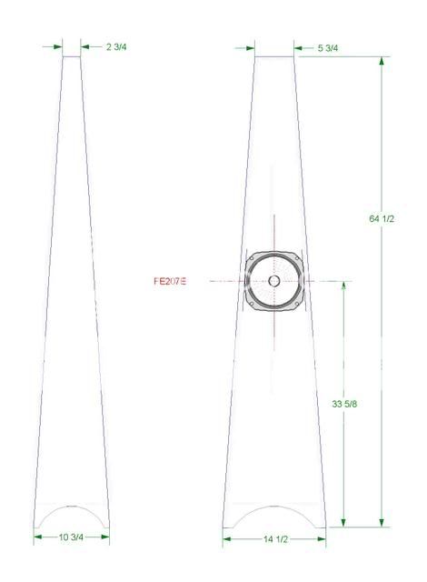
I used some 1/8 material I had laying around to determine these measurement to cut out the panels. The 1/8 pattern later came in handy for cutting dampening material and figuring layout for the brace for the driver.
As others have stated a table saw is useless for this enclosures except for cutting the endcaps out. The tool I found most valuable was my router.
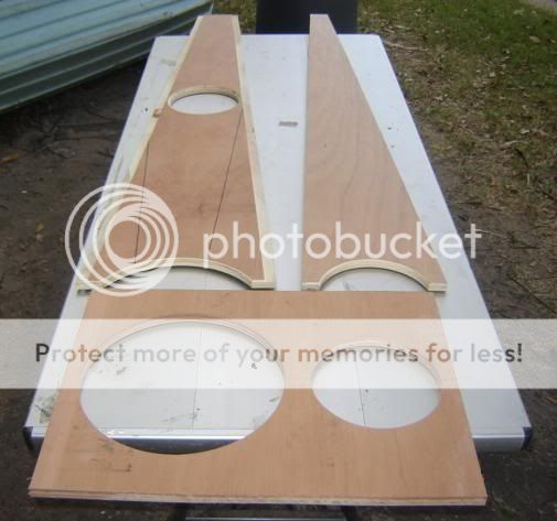
I would recommend cutting one of each panel exactly then use it to build the others. I layed my pattern on the boards to cut then scribed out then cut them outside of the lines(recommend drawing one side of pattern then flip patten to draw the other to make sure both were the same angle, hope that make sense). I then used a straight edge as a quide for the flush trim bit in my router to get a strait 90 degree cut.
Make sure you draw a centerline down the long length of the board before cutting out the arch on the bottoms. I used a scrap piece of wood and cut a 12 1/2 and 8 inch hole in it for a pattern for the arches. Again draw a centerline before cutting the holes out. Mark your side panel at 3 1/8 from the bottom then line up the centerlines of the circle pattern to this mark and draw out the arch. The centerlines should keep your arches square. Cut excess outside of the line with a jigsaw then clamp pattern down and use flush trim bit to cut to your line.
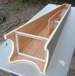
The first pic is oversized by 1/4 inch. Reason being is I used a 3/4 straight cut bit in the router with a staight edge guide on the router to prep the front and back panels for glueing (see second pic top left panel) Staightedge was adjusted to 7/8 inch and the depth of the cut was 1/8 inch. This made glue up a breeze. You will later need to fush trim th 1/8 excess after your panel have been glued up.
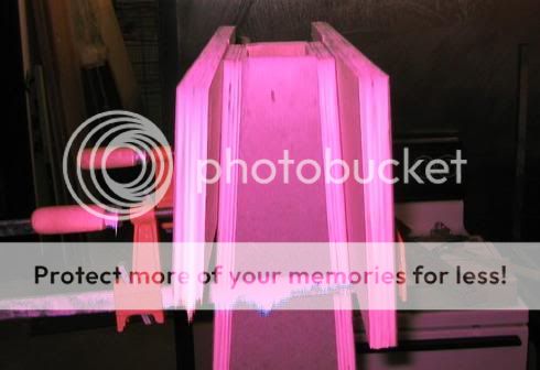
I used all 4 sides to glue the panels together but did not glue the back. Note that all sides of the side panels were cut at 90 degrees. The bottom I didn't worry about, see third pic (bad batteries) for how the top was done. I used a clamp to hold the back panel to the three sides that were glued and place the enclosure on a level surface. Note in pic that two boards with straight edges were clamped above the top cap and leveled. I used this with the router and straight bit with the depth set to a 64 3/8 height mark scribed to one of the side panels.
Last pic show everything glued except the rear panel. I elected to use the bottom for an access point in the future. This also made installing the port and banana plugs easier. A table saw was used for cutting out the caps. 1 degree and 4 degree cuts prove to be close enough. Note that having a centerline on the baffle before glueing and cutting the arches helped in positioning the driver brace. Also note that the top bottom caps and the driver brace are short 1/8 inch to allow the rear panel to be glued in.
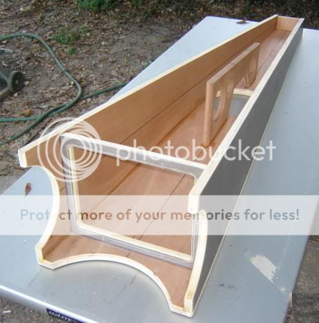
This isn't everything to the build but should provide some tips that helped me along the way 😀.
I played with the dampening before glueing the rear panel and hope to have the drivers installed this evening. Working today and tomorrow along with Sunday and Monday night football will delay listening until Tuesday evening. Hope to have some listening impressions before going out of town next weekend starting Thursday. The drivers have close to 200 hrs on them already. Also looking forward to getting some phase plugs, thanks Dave.
Brad
As others have stated a table saw is useless for this enclosures except for cutting the endcaps out. The tool I found most valuable was my router.
I would recommend cutting one of each panel exactly then use it to build the others. I layed my pattern on the boards to cut then scribed out then cut them outside of the lines(recommend drawing one side of pattern then flip patten to draw the other to make sure both were the same angle, hope that make sense). I then used a straight edge as a quide for the flush trim bit in my router to get a strait 90 degree cut.
Make sure you draw a centerline down the long length of the board before cutting out the arch on the bottoms. I used a scrap piece of wood and cut a 12 1/2 and 8 inch hole in it for a pattern for the arches. Again draw a centerline before cutting the holes out. Mark your side panel at 3 1/8 from the bottom then line up the centerlines of the circle pattern to this mark and draw out the arch. The centerlines should keep your arches square. Cut excess outside of the line with a jigsaw then clamp pattern down and use flush trim bit to cut to your line.
The first pic is oversized by 1/4 inch. Reason being is I used a 3/4 straight cut bit in the router with a staight edge guide on the router to prep the front and back panels for glueing (see second pic top left panel) Staightedge was adjusted to 7/8 inch and the depth of the cut was 1/8 inch. This made glue up a breeze. You will later need to fush trim th 1/8 excess after your panel have been glued up.
I used all 4 sides to glue the panels together but did not glue the back. Note that all sides of the side panels were cut at 90 degrees. The bottom I didn't worry about, see third pic (bad batteries) for how the top was done. I used a clamp to hold the back panel to the three sides that were glued and place the enclosure on a level surface. Note in pic that two boards with straight edges were clamped above the top cap and leveled. I used this with the router and straight bit with the depth set to a 64 3/8 height mark scribed to one of the side panels.
Last pic show everything glued except the rear panel. I elected to use the bottom for an access point in the future. This also made installing the port and banana plugs easier. A table saw was used for cutting out the caps. 1 degree and 4 degree cuts prove to be close enough. Note that having a centerline on the baffle before glueing and cutting the arches helped in positioning the driver brace. Also note that the top bottom caps and the driver brace are short 1/8 inch to allow the rear panel to be glued in.
This isn't everything to the build but should provide some tips that helped me along the way 😀.
I played with the dampening before glueing the rear panel and hope to have the drivers installed this evening. Working today and tomorrow along with Sunday and Monday night football will delay listening until Tuesday evening. Hope to have some listening impressions before going out of town next weekend starting Thursday. The drivers have close to 200 hrs on them already. Also looking forward to getting some phase plugs, thanks Dave.
Brad
ecir38 said:Note that having a centerline on the baffle before glueing and cutting the arches helped in positioning the driver brace.
Itr looks like you put the holey brace dead centre... for future reference it is best put just off-centre (ie one edge of the brace on the centre line is how we usually line it up)
dave
Hi Steve,
I couldn't get any of the picks for the drawings of the "Metronome" to open. Can you provide a pdf or put up another URL?
Regards, red
I couldn't get any of the picks for the drawings of the "Metronome" to open. Can you provide a pdf or put up another URL?
Regards, red
Thanks Dave, mental note madeplanet10 said:
Itr looks like you put the holey brace dead centre... for future reference it is best put just off-centre (ie one edge of the brace on the centre line is how we usually line it up)
dave
Where are you trying to open them? If you are trying herered2erni said:Hi Steve,
I couldn't get any of the picks for the drawings of the "Metronome" to open. Can you provide a pdf or put up another URL?
Regards, red
http://www.frugal-horn.com/metronome-table.html
you really don't need pics just use the variations tables.
Which driver are you thinking of using?
BR
Dave, have you ever tried the war paint on the FE207E. I did it to my FE127e's with good results and was just wondering. Would the 9mm and 17mm marks apply to this driver too?
BR
BR
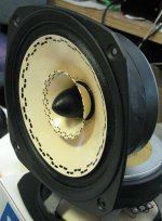
ecir38 said:have you ever tried the war paint on the FE207E. I did it to my FE127e's with good results and was just wondering. Would the 9mm and 17mm marks apply to this driver too?
The trifoil pattern only applies to the FE126/127 cone.
I am on proto 9-12 as we speak.
Similar treatment to FE206 elicited this response from a client
FE20eN) Dave, make no mistake. This 206En is killer. You can take my opinion for what it's worth, but your driver doesn't just compare to the ESR, it smokes it!
Jeff C
so you can look forward to milking much more preformance out of your 207 than just what the phase plugs will do.
dave
(picture is a 206 i couldn't quickly find a 207 pic) BTW the 1st pair of FE207eN are Marc Englands, he has made some comments on the Curvy Change thread
Attachments
Thanks again, I saw the 206 pic on the fullrange forum earlier.
Found the curvy chang review of the driver, wish marce had a chance to hear them without the enable on them first.
http://www.diyaudio.com/forums/showthread.php?postid=1354867#post1354867
Might just do this first as a precoat untill I can get to the enable process
http://www.diyaudio.com/forums/showthread.php?postid=1398766#post1398766
Hope I didn't mess too much up by having the brace centered, should have known better 😡 since I built the Fonken floorstander that way. This comment has me a little worried now.
http://www.diyaudio.com/forums/showthread.php?postid=1401499#post1401499
Would you by chance have the pattern for the 206 / 207 handy? If not that pic should work.
BR
ecir38 said:Found the curvy chang review of the driver, wish marce had a chance to hear them without the enable on them first.
He does have a set of stock FE166 which gives him the general idea.
Might just do this first as a precoat untill I can get to the enable process
Worthwhile for sure -- dame as on the FE127
Hope I didn't mess too much up by having the brace centered, should have known better 😡 since I built the Fonken floorstander that way. This comment has me a little worried now.
You can band aid it by fitting a small piece next to the holey brace on one side only (say 18mm x 2"). The dimensions at this point are not that large and are a trapezoid so issues will not be as significant as with a rectangular box.
Would you by chance have the pattern for the 206 / 207 handy? If not that pic should work.
Here is my pattern secret... i take a generic pattern, scale it every which way, print them all out and then use the one that fits. A3 on the outer edge, A5 on the whizzer edge, 56 for the voice coil & phase plug, and A3 or A4 (on edge) for under the whizzer (use the spots on the whizzer as a template). Under the whizzer is a real pain and don't expect to be super tidy, have lots of q-tips handy, but a 207 is a lot easier than a 167.
dave
Should this piece extend to the rear panel? I do have a minute gap between the driver and brace where I used some blue tac if that helps.planet10 said:
You can band aid it by fitting a small piece next to the holey brace on one side only (say 18mm x 2"). The dimensions at this point are not that large and are a trapezoid so issues will not be as significant as with a rectangular box.
Thanks, I have the generic pattern already. Behind the whizer does look to be the tricky part 😉.planet10 said:
Here is my pattern secret... i take a generic pattern, scale it every which way, print them all out and then use the one that fits.
BR
ecir38 said:Should this piece extend to the rear panel? I do have a minute gap between the driver and brace where I used some blue tac if that helps.
No time to draw a pic, but it is a piece that goes edge on to the baffle/cab rear and moves the apparent middle of the holey brace off to one side (ie makes the unsupported panel on one side the thinkness of the new piece smaller) They would run vertically the height of the hoely brace (front one would be 2 pieces (no need to obscure the driver anymore)
dave
- Home
- Loudspeakers
- Full Range
- The Metronome