janneman said:The guy who will make commercial spaceflight a reality. The man who built the commercial equivalent of the space shutle in 2 years with 20million US $. I need 200k to set aside for my flight. Any sponsors?😉
Before you put your 200K down, this thing is not really the equivalent to the space shuttle, it can only go to the outer layer of the atmosphere (and back) not real space. I think it was about 100km (mile?), an arbitrary definition of outer space.
It was still an incredible achievement. 😀
The next step is a space shuttle equivalent.
The EMF ALWAYS leads to a current. It takes the same path as that current from the amp. If there was no path, your amp output current also would have no place to go. The EMF simply is a voltage source connected to some impedance and will cause current.
Hi Jan,
this is only be possible with a voltage source connected to the speaker. If you have a signal controlled current source there is no return path for the EMF. Althought EMF results in voltage on the amp output EMF leads to no current. But as all (available) speakers are designed to operate with a voltage source High-Z power amps do not exist in the audio industry.
Or have I misunderstood you?
To all,
I cannot see, what the EMF has to do with distortion on global nfb or no nfb concepts. If an amp is driven forward or backwards the discussion should be about nonlinearities. EMF and speaker damping can explained by linear network analysis.
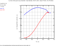
I've attached the simulation results of the transfer characteristic of an optimised triple EF otputstage which is driven by current source (typical VAS stage). The blue graph shows the normalised transfer characteristic the red line the output voltage vs. differential driving curret. As you see, the output stage is much less linear as often stated. The sharp bends at -50ua and + 40ua shows the limiting effects, as the amp is connected to a +/-50V power supply. Loading is 8ohms, with 6 MJL1302/MJL3281 paralleled. Bias is about 75 ma each transistor which results in an overall bias of about 0.5amps
Although this is a complementary design the transfer characteristic is not symmetrical. This also shows that a complementary design does not necessarily eliminates even order harmonics.
Attachments
I dont understand this. What is the meaning of quote above?Here I'm opening a can of worms - a BIG one!
Hi All,
My iron has been smoking again, and the attached amplifier has been playing some music from Luther Vandross, who sadly passed away last week. His some of his '80s music has suberb audio quality.
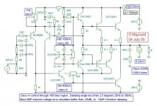
I had posted a JLH based class-A//AB amplifier circuit, where class-A operates at all times and thus maintains continuity of correction for waveform errors that can arise through class-AB transconduction non-linearities.
It ran well but in common with single input circuits suffered output zero drift up to +/-50mV. A differential input cures this, but then stability becomes a concern.
I have found that the input filter shown here, with 10nF across the base-emitter junction of the output sensing input differential transistor, together overcome stability issues without impairing audio.
I find that Miller and internal stabilising capacitors can have an audible impact, and this is why I do not use them, nor a mirror on the differential, here.
The phase response is +/-2 degrees 20Hz to 30kHz, and the damping remains virtually resistive throughout the same range without introducing phase shifted error wrt to input from loudspeaker generated back-EMF. With 10mF in place of 4m7F on the feedback resistor the phase response could be +/-1 degree from 20Hz to 20kHz, but would the difference be audible ? (Nothing noticed so far.)
Thus, with good construction practice / psu, all distortion at normal listening levels should be <0.01%, *and not just the measurable thd figure*.
Unfortunately, because dc decoupling Cs are still used, there remains a partial power-up thump.
Testing continues.
Cheers ........ Graham.
My iron has been smoking again, and the attached amplifier has been playing some music from Luther Vandross, who sadly passed away last week. His some of his '80s music has suberb audio quality.
I had posted a JLH based class-A//AB amplifier circuit, where class-A operates at all times and thus maintains continuity of correction for waveform errors that can arise through class-AB transconduction non-linearities.
It ran well but in common with single input circuits suffered output zero drift up to +/-50mV. A differential input cures this, but then stability becomes a concern.
I have found that the input filter shown here, with 10nF across the base-emitter junction of the output sensing input differential transistor, together overcome stability issues without impairing audio.
I find that Miller and internal stabilising capacitors can have an audible impact, and this is why I do not use them, nor a mirror on the differential, here.
The phase response is +/-2 degrees 20Hz to 30kHz, and the damping remains virtually resistive throughout the same range without introducing phase shifted error wrt to input from loudspeaker generated back-EMF. With 10mF in place of 4m7F on the feedback resistor the phase response could be +/-1 degree from 20Hz to 20kHz, but would the difference be audible ? (Nothing noticed so far.)
Thus, with good construction practice / psu, all distortion at normal listening levels should be <0.01%, *and not just the measurable thd figure*.
Unfortunately, because dc decoupling Cs are still used, there remains a partial power-up thump.
Testing continues.
Cheers ........ Graham.
Attachments
To all,
I cannot see, what the EMF has to do with distortion on global nfb or no nfb concepts. If an amp is driven forward or backwards the discussion should be about nonlinearities. EMF and speaker damping can explained by linear network analysis.
Hi, Bocka,
Offcourse the majority of speaker's cone position is determined by the amp itself. Maybe 99.9% of whats it's cone's excusion position is determined by the amp correctly.
But speakers (any speaker) are not having infinite speed. And another thing, every movement in voice coil (besides music program, that is the residual movement from a certain excursion position) will give back EMF (while the major EMF is given by the amp+voice coil).
If this back EMF is random towards original music, offcourse the feedback system will result in more high order distortion due to back EMF.
It is a very tiny energy, but as Jean Hiraga wrote, our ear can hear its effect as "pleasant" or "not pleasant" sound reproduction, even if the energy is so small.
Back EMF is quite imaginary, someone here maybe even ask how to proove that it existed at all.
lumanauw said:
But speakers (any speaker) are not having infinite speed. And another thing, every movement in voice coil (besides music program, that is the residual movement from a certain excursion position) will give back EMF (while the major EMF is given by the amp+voice coil).
If this back EMF is random towards original music, offcourse the feedback system will result in more high order distortion due to back EMF.
It is a very tiny energy, but as Jean Hiraga wrote, our ear can hear its effect as "pleasant" or "not pleasant" sound reproduction, even if the energy is so small.
Back EMF is quite imaginary, someone here maybe even ask how to proove that it existed at all.

Hi, Mr. Maynard,
What is the purpose of the most right-down NPN transistor C3281? Never see it anywhere before.
What is the purpose of the most right-down NPN transistor C3281? Never see it anywhere before.
Graham Maynard said:Hi All,
My iron has been smoking again[snip]Testing continues.
Cheers ........ Graham.
Hi Graham,
What is the purpose of the transistor 2SC3281 in the lower-right-hand corner, the one that has the collector to the output and the emitter to the -50V? Does it function in the bias loop?
Jan Didden
For him impassioned of mathematics ( and of the simulators ) a link of teorical Speaker view...
http://www.arcavia.com/kyle/Equations/index.html
Ciao
Mauro
http://www.arcavia.com/kyle/Equations/index.html
Ciao
Mauro
mastertech said:guys the speaker isnt a generator
Then why it may be used as a microphone?
lumanauw said:
I dont understand this. What is the meaning of quote above?
It means that this post could atract lots of arguments against it...
Is there a model for speaker that can "produce voltage"also, instead of treating speaker as a device that only "receive voltage" without any reaction at all?For him impassioned of mathematics ( and of the simulators ) a link of teorical Speaker view...
Well, a normal speaker model has a parallel combination of capacitor and inductor. This is what produces the back-EMF. If on the other hand you want to replicate the microphonic aspect, then just put a voltage source in series with the model.lumanauw said:
Is there a model for speaker that can "produce voltage"also, instead of treating speaker as a device that only "receive voltage" without any reaction at all?
Back in my high-school days EMF was stated as being 'electromotive force', but the teachers always applied the term to potential (voltage) sources.
However a source of EMF (battery/generator/loudspeaker) is just that, it makes current flow through its own resistance and develops a potential (voltage) across circuit resistance or impedance.
An EMF is *not* always a leading voltage, because, depending on circuit reactivity, voltage might not develop until after current flows, as into a capacitor (Mosfet gate).
I think someone has already explained that the amplifier drives the loudspeaker with voltage. The voltage causes current to flow through the loudspeaker. The loudspeaker drivers motor and generate back-EMF, this electromotive force modifies in time the loudspeaker current that flows due to the amplifier's voltage output (which is also changing in time).
The back-EMF from a loudspeaker cannot generate much voltage across a very low resistance, as with an amplifier that has a high damping factor, but if the amplifier has a series reactive component within itself, then its voltage output will be modified no matter how low its thd as measured using a purely resistive load.
The problem with loudspeaker system generated back-EMF is the (crossover/motor) delay, as shown by Rodolfo in Post#269.
Under steady sinewave conditions there can be a lead or a lag at different frequencies, but this does not show the real currents that flow due to circuit reactivity and back-EMF generation (and voltage distortion due to reactive amplifier outputs) with changing waveforms; the resulting current changes in time from an initial value to the one measurable under steady sinewave conditions calculatable via T-S parameters.
Look at the V(vest)+v(vesw) plots relating to the piston velocity. It is voice coil motion that generates the back-EMF. Some loudspeaker system back-EMF is generated within the first 90 degrees of drive, at another frequency it might not arise until after a full cycle of drive.
This is how lagging and leading back-EMF development arises, as illustrated in the -V(vi)/i(v1) plots.
Hi David and Jan,
I'm not on Broadband, so I mostly check mornings and evenings.
The VAS/driver of a complementary push-pull output stage operates in class-A.
My lower 2SC3281 (been on heatsink for yunks and hasn't blown or I would be using 2SC5200) is a Darlington to the VAS/driver and draws near constant class-A current through itself and the upper the upper output transistors.
At lower levels the output is class-A. When the load requirements become larger it acts in parallel with the class-AB output stage as a driver controlled class-A correction device.
I suppose when compared with the Quad 'current (class-B) dumper', this circuit makes the class-AB output stage into a 'current helper' amplifier, however, here it works in real time without any reactive lag due to chokes or the output bridging that is necessary to compensate for class-B bipolar 'dumping' delays.
Cheers ........ Graham.
Graham Maynard said:..... Some loudspeaker system back-EMF is generated within the first 90 degrees of drive, at another frequency it might not arise until after a full cycle of drive.
This is how lagging and leading back-EMF development arises, as illustrated in the -V(vi)/i(v1) plots.
.....
In another thread I showed in spreadsheet and for a simple passive crossover, how instantanous device voltage and current relate for different frequencies. Anyone interested may substitute for example actual simulation impedances from my posted results (#269) .
Interestingly, Andy_c work on simulated output stage source impedance (before feedback) at various output DC voltage levels provided at least for me an unexpected insight.
For the case of resistive load, voltage and current zero-crossings coincide at 0V output. This is not the case for a more typical reactive load as can be seen in the first link mentioned above. This means for example, that a current zero crossing might occur at an output voltage different from 0, in fact quite different.
The unexpected insight, is we tend to (at least I used to) associate crossover distortion with low level signals. What this shows is it can effectively appear even in the presence of large power outputs.
Consider for example a fairly typical case, a large amplitude low frequency component to which is superimposed a very small signal (what some refer to as microdetail). As it is bound to happen, load phase angle at the low frequency might be fairly large, meaning there will be a current zero crossing at an important output composite voltage, implying crossover induced intermodulation on the low level signal.
Rodolfo
(PS. Oh well.... more ammo for class A militants)
Re: Re: Detrhoning back EMF
Admittedly, I was lousy on terms....
Medium velocity and pressure are related by characteristic medium impedance for plane waves (far field).
Actual cone velocity and pressure distributions are far more messy. A good place to delve on this is in the "Physics of sound" page by Art Ludwig.
Warning: This site displays explicit math contents.
In the far field, for a piston, and on-axis, it is true sound pressure relates for sinusoidal exitation with (piston) velocity times (2*pi) frequency, which is acceleration.
Rodolfo
moamps said:Very educative thread.
Voice coil acceleration equals sound pressure.
....... its far-field sound presure level will be proportional to the cone acceleration."
.....
Admittedly, I was lousy on terms....
Medium velocity and pressure are related by characteristic medium impedance for plane waves (far field).
Actual cone velocity and pressure distributions are far more messy. A good place to delve on this is in the "Physics of sound" page by Art Ludwig.
Warning: This site displays explicit math contents.
In the far field, for a piston, and on-axis, it is true sound pressure relates for sinusoidal exitation with (piston) velocity times (2*pi) frequency, which is acceleration.
Rodolfo
janneman said:Nelson, I beg to disagree. The EMF ALWAYS leads to a current. It takes the same path as that current from the amp. If there was no path, your amp output current also would have no place to go. The EMF simply is a voltage source connected to some impedance and will cause current. Changing the amp from voltage output to current output changes the paths available for the EMF-induced current, but not the principle. There is always at least ONE path available, both for the amp current and the EMF, and that is the voice coil.
Since we have been referring to back EMF, generated by the
motion of the speaker, I have to insist that it needs something
to complete the loop from one end of the voice coil to the other.
A current source will not do this for you, as its impedance is
infinite, and so the back EMF produces no current, and thus
no force.
lumanauw said:I notice in F2, NP is putting 15ohm parrarel inside to the amp's output. Is this for providing path for back EMF that doesn't go into the amp itself, making better sound? But this amp has no feedback.😀
My view is that the amp doesn't particularly care about the back
EMF. The intrinsic source impedance of an F2 is about 700 ohms,
but I found from customer experiences with the F1 that with
Lowthers and whatnot they usually want to see something like
15 ohms or less, and a lot of people don't want to bother putting
even so much as a resistor across the terminals. With higher
resistance values and a back-loaded enclosure, anything greater
assures you of a peak in the bass region, so I put three 47 ohm
power resistors in parallel at the output. They are removable.
"Then why it may be used as a microphone?"
Hi jorge
i dont know, you tell me
maybe is because it has the same structure/principle as the speaker
microphone could make a high power electric gen according to
you couldnt it?
cheers
Hi jorge
i dont know, you tell me
maybe is because it has the same structure/principle as the speaker
microphone could make a high power electric gen according to
you couldnt it?
cheers
By the principle of reciprocity, every speaker is a microphone
and vice versa, and yes, they are generators. You could
probably read a book with the electricity generated by
a speaker listening to a Saturn 5 launch.
😎
and vice versa, and yes, they are generators. You could
probably read a book with the electricity generated by
a speaker listening to a Saturn 5 launch.
😎
- Status
- Not open for further replies.
- Home
- Amplifiers
- Solid State
- The many faces of distortion