The first thing I do with every new design, is to look out for third party measurements.
In this case, luckily both drivers are done by the same guy;
Peerless TC9FD18-08 | HiFiCompass
ScanSpeak 10F/8424G00 | HiFiCompass
Keep in mind he uses output voltage as reference, not SPL lever, so there are some errors here and there. (meaning it's not totally apples vs apples)
If it wasn't for those mechanical issues, I would consider the TC9 as one of the best out there.
Especially price-performance ratio.
Well, not totally true, Sica, LaVoce and Beyma have some very nice 3 inch fullrange units as well.
Incl demodulation rings and all.
edit: good thing to mention Hificompass also sometimes adds an highpass filter on the measurements, in case of the TC9, HP 150Hz
So watch for these things as well. It's not always very clear.
Last edited:
I have seen those measurements, and all others might I say.
The 10F tested here is the mid range 10F, I'm using the 10F 8414.
Slightly different motor on that 10F. But the biggest difference being the closed spider area vs the open 8414.
Totally agree on the verdict for the TC9. If I didn't have 6 failed drivers within a time span of one month, I would never have gone for the 10F upgrade.
I was happy with the performance of this low priced marvel, with lots of small but important things like the copper cap and pentacut NRSC cone.
Scan Speak designed it and use the exact same technology in the 10F, which really is an upgraded version of the fiberglass TG9 and it's predecessor.
They started making the 10F line one year after the split of Peerless/Vifa and Scan Speak.
Last edited:
Oh sorry, apologies, those parts numbers are so confusing at times 🙁
But I assume those measurements are quite similar.
Based on just purely these measurements I would have also said TC9 every day any day.
But it goes to show some experience I would like to share often to other people, having professional experience with speakers in bigger numbers.
There is often more than just raw performance.
Also that price doesn't say anything.
I know brands that are even much more expensive, but their failure rate and all other problems are just things I never would like to have.
As an hobbyist that is not really a big issue often.
Well unless you have 50 of the same 😀 😀 😀
My only real point was that it looks like noise in the measurement and for me I don't want to try and draw too many conclusions from data that has obvious noise in it.Never really did figure out the why, but right now it's different between 10F and TC9, that's for sure.
Obvious noise or not, it's using the exact same stimulus as the 10F measurements used.
Probably under powered for the TC9 to get rid of it, but I've never used anything else.
It's still visible in your own measurements, the 10F would look cleaner there. What's causing it, I don't know. I'm guessing differences in motor construction. That's all I said 😉.
Probably under powered for the TC9 to get rid of it, but I've never used anything else.
It's still visible in your own measurements, the 10F would look cleaner there. What's causing it, I don't know. I'm guessing differences in motor construction. That's all I said 😉.
Were the measurements taken at the same time on the same day or are the TC9 measurements from when you originally made them? I am maybe wrongly assuming they were old TC9 measurements being compared to new 10F.
It is an old TC9 measurement (from 7 years ago, when the driver was new), but I can do a new TC9 vs 10F measurement.
Let me run into the garage and test the TC9 vs 10F.
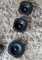
I'll pick an old TC9, a newly bought TC9 and a 10F for this test.

Reserve TC9 drivers and a couple of old ones that I exchanged
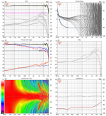
Here are the DUT's:

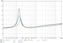
Their impedance:

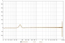
New TC9 group delay tab:

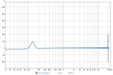
Old TC9 group delay tab:

New 10F group delay tab:

What do you know... 🙂 they look very similar today when measured one after the other. 😱
So it's temperature related? I've seen big differences with the array measurements once the temperature goes below 20 degree C.
Thanks for the push fluid!
Be careful with those conclusions, wesayso! Guess again 😀.
Let me run into the garage and test the TC9 vs 10F.
I'll pick an old TC9, a newly bought TC9 and a 10F for this test.
Reserve TC9 drivers and a couple of old ones that I exchanged
Here are the DUT's:
Their impedance:
New TC9 group delay tab:
Old TC9 group delay tab:
New 10F group delay tab:
What do you know... 🙂 they look very similar today when measured one after the other. 😱
So it's temperature related? I've seen big differences with the array measurements once the temperature goes below 20 degree C.
Thanks for the push fluid!
It's still visible in your own measurements, the 10F would look cleaner there. What's causing it, I don't know. I'm guessing differences in motor construction. That's all I said 😉.
Be careful with those conclusions, wesayso! Guess again 😀.
Attachments
Last edited:
The temperature thing (and same day thing) is far fetched. Unless you're measuring in a room were the temperatures heavily fluctuate.
But that wouldn't be so good for the room itself lol.
Although still, my measurements during summer are not so different compared to regular room temperature measurements.
With smaller drivers the tolerances are always a little bigger.
Don't really see the purpose of the group delay here?
But that wouldn't be so good for the room itself lol.
Although still, my measurements during summer are not so different compared to regular room temperature measurements.
With smaller drivers the tolerances are always a little bigger.
Don't really see the purpose of the group delay here?
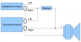
My impedance measurement setup is an old Vista laptop with REW on it and a rigged up cable like this:

I've seen the impedance peak vary (in position and value) with temperatures lower than 17-18 degree. I've not seen it vary that much with higher temperatures than room temperature and above.
Why do I look at group delay tabs during an impedance measurement? Because it's there.
I've looked at all tabs in every measurement from the start to see if I can learn something from it.
Does it make sense to look at it? Not that much, if there's no new information there 😉. It was the cause for me to use a conjugation network for my arrays. Be it right or wrong.
Attachments
Whats the value of rsense?
Are you sure your output impedance of headphone output is low enough?
Are you sure your output impedance of headphone output is low enough?
Don't remember what the rsense is, I think it was 100 ohm and tight tolerances.
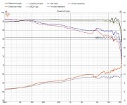
What matters to me is that I can measure a resistor and get the right value. The same goes for caps and coils. It gets me close enough if the impedance of a driver matches the factory shape and value (on average). I measured the filters with caps and coils and compare that to simulated values. It works out very well, especially considering the tolerances of the components used. So that builds up trust that I can have confidence in this simple impedance jig. I've used it many times over the years. Temperature is a factor though.

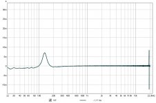
The impedance peak doesn't line up completely here, but I'm not that worried. As I can compare it between drivers and have a frame of reference. My garage temperature today was 18 degrees Celsius. I've seen it shift to either side with different temperatures. This driver also is new with no play time.
My mic is calibrated though, as that is much more important to me.
What matters to me is that I can measure a resistor and get the right value. The same goes for caps and coils. It gets me close enough if the impedance of a driver matches the factory shape and value (on average). I measured the filters with caps and coils and compare that to simulated values. It works out very well, especially considering the tolerances of the components used. So that builds up trust that I can have confidence in this simple impedance jig. I've used it many times over the years. Temperature is a factor though.
The impedance peak doesn't line up completely here, but I'm not that worried. As I can compare it between drivers and have a frame of reference. My garage temperature today was 18 degrees Celsius. I've seen it shift to either side with different temperatures. This driver also is new with no play time.
My mic is calibrated though, as that is much more important to me.
Attachments
Last edited:
Ah, ok makes sense now.
Laptop outputs are unfortunately to low to give any useful data around the Fs.
They are ok for just passive filters and such.
Depending on the suspension, but some drivers can shift very significantly around the Fs. I can show some tests I have done with a couple of drivers.
Basically you just have to look at the impedance, and get the Qms, Qes, Qts and Fs from the measurements (you don't need to add any mass)
I do realize that, but I don't really need those parameters. The only thing that's important to me right now is that my filters, that filter way above the FS peak, work acceptable.
I'm not basing any wanted frequency curve on the driver parameters. All of the shaping of the frequency curve is done with DSP filtering. What I do need to know if the drivers are ok to work with, so comparing one to the other, and more recently if the general trend is acceptable enough to work for my filter deduction. And that's working fine.
Most people use the driver parameters to shape the frequency response and determine box size and what not. I don't in this case. So that's why it isn't that important to me, except where I use filtering.
As long as that part of the curve lines up with factory data (free air), I'm good to go. The only other use of impedance plots is to find the enclosure size/shape related blips.
Most people here have a hobby of building lots of speakers. I've only build this one with no other plans to change my hobby. Thus I did not have a need for that kind of accuracy.
I almost bought a DATS 6 years ago but figured I do not really need it. At that time I was between jobs and did not really have the budget. I could do without and quite frankly, I still can. As said, I probably need more power to get more accurate measurements, but as a tool to compare one to the other this works well enough.
Last edited:
Ah, ok no problem.
Yeah these measurements this way are accurate from roughly 1,5-2 x Fs (from the datasheet).
If you wanna just see if they are ok, just measure them relative from each other.
If they all fall within the same ballpark, it will be just fine.
Yeah these measurements this way are accurate from roughly 1,5-2 x Fs (from the datasheet).
If you wanna just see if they are ok, just measure them relative from each other.
If they all fall within the same ballpark, it will be just fine.
Slightly edited and updated filters for the 10F. Due to the slight differences in the impedance curves between
TC9 and 10F the filters reacted slightly different too. With the altered filters the top end is behaving a tiny bit better.
All it takes are 7x 10 nF capacitors to upgrade the filters for each array (3 filters need editing).
The 0.01uF Vishay MKP 1837 will do that job nicely.
There's still some differences but that's so minor I won't bother changing the components to alter that.
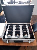
Here's the TC9 six-pack in comparison:
Attachments

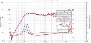
Spinorama style graph... Reference angle is set to 10 degree as that is my preferred listening angle.
Absorbing is set to 20 dB for floor and ceiling in this graph, as to reflect anechoic like conditions.
Attachments
Last edited:
Had a strange week... I finally sold my oldtimer after 13 years of daily use (which stopped a few years ago) and 16 years of ownership in total. Mixed feelings really. I sold it to my mechanic, who kept on nagging me for at least a few years. I've always done all maintenance myself on my Porsche (that's how I could afford it). It's when I got an Audi TT to take over the task of daily driver that I decided to pay someone else to work on it. (getting older 😱)
I met this guy a few years back and I trust him to do the work on my car(s), which makes me happy he's the one that will take care of my beloved car from now on.
The car is in high need of some love and care after being subjected to all types of weather (and salt on the roads in winter time 🙁) and started to show it's age (build in 1982). I know what that entails, I've done some full restorations in my younger days. Not looking to renew that hobby, I've got my hands full already.
I did keep the Genesis series III 4 channel and matching Stereo 60. Together with the Vifa XT tweeters and the set of Herz ML1600 woofers and a JBL sub.
Even though I did keep the Pioneer P88RS II head-unit too I'm dreaming of using the above amps and drivers with a Pioneer P99RS so I can add some ambience speakers in the back for my '99 Audi TT. (It's an active 4 way capable unit, I need to look trough the manual to see if it allows me enough freedom to do something like that)
Attachments
Last edited:
- Home
- Loudspeakers
- Full Range
- The making of: The Two Towers (a 25 driver Full Range line array)