Maybe I should have used 50 matched pairs (lol)
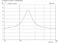
WinISD impedance using the averaged FS of 138 shows this graph for a box of 51 liter:

Resonance at 189 Hz, so the damping is giving me 21% more virtual volume? 😀
I only used what I needed to get rid of all impedance wiggles in my test box. I've had lower results
of the FS peak with different combinations but the combination I ended up with was the best to smooth
out the curve. Seems to have worked really well.
WinISD impedance using the averaged FS of 138 shows this graph for a box of 51 liter:
Resonance at 189 Hz, so the damping is giving me 21% more virtual volume? 😀
I only used what I needed to get rid of all impedance wiggles in my test box. I've had lower results
of the FS peak with different combinations but the combination I ended up with was the best to smooth
out the curve. Seems to have worked really well.
Last edited:
I have made a RCL network that eliminates the impedance peak, so no plots from me sorry.
It has a beneficial impact on the sound of the speakers. No much but worth the effort.
Koldby
It has a beneficial impact on the sound of the speakers. No much but worth the effort.
Koldby
Hi Koldby, but it still would be fun to see a measured impedance plot with that RCL network in place. I had thought about doing a RCL network. I still might. But I am quite curious to see a plot of it. What does it do for the sound?
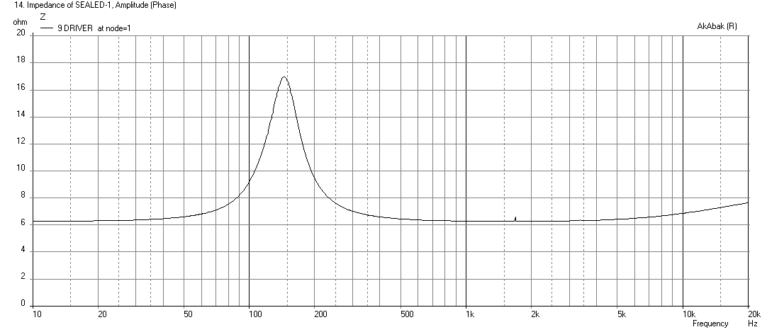
I think the thing to realize is that the wiggles are mostly the result of the interaction of the driver with the cabinet resonances and not due to variability on driver T/S params. I just ran a sim of a 9 driver array with variable T/S where I added "noise" to: fs, Qms, Qes, Mms, and Re of the TC9FD's. The impedance looks smooth - well integrated electrically. So the ripples are probably due to the acoustical coupling of the drivers with the enclosure.
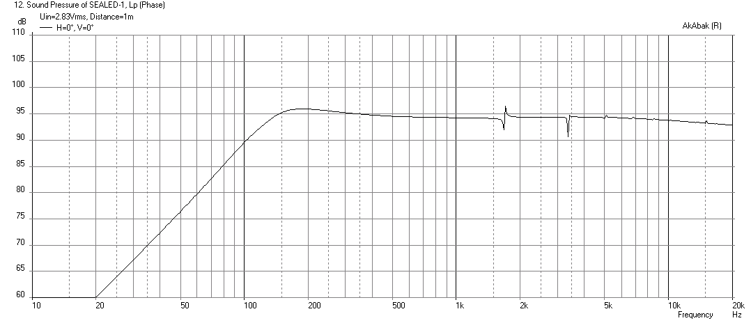
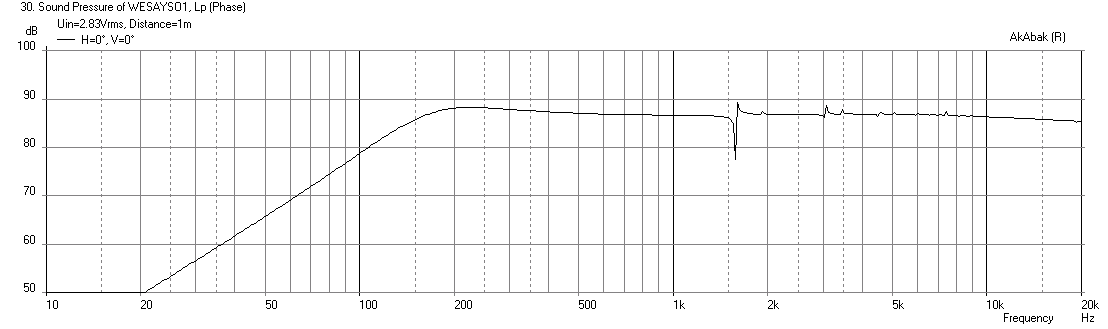
Here is predicted SPL:
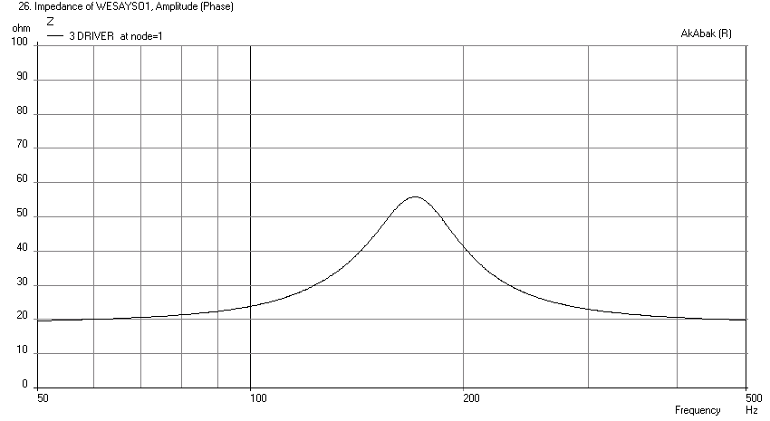
Predicted Impedance - no wiggles:
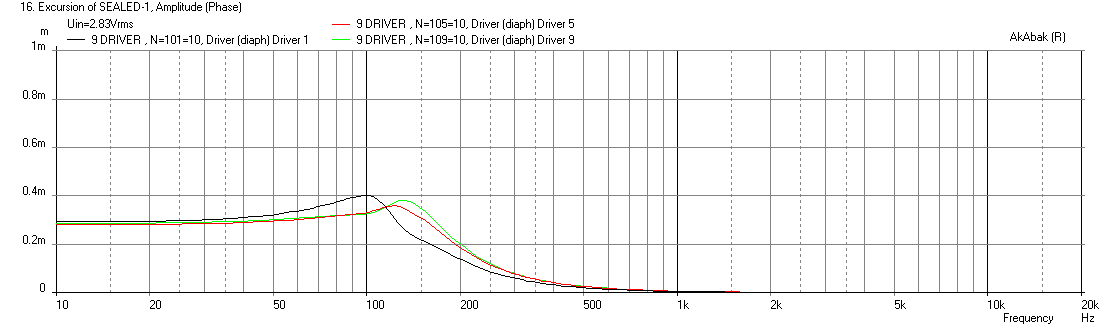
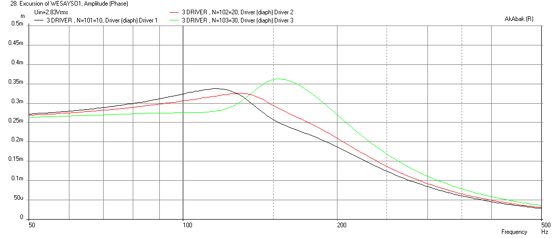
Predicted cone displacement for drivers 1, 5, 9 - note they are different since TS is different:
For anyone wanting to play with Akabak...
Here is predicted SPL:
Predicted Impedance - no wiggles:
Predicted cone displacement for drivers 1, 5, 9 - note they are different since TS is different:
For anyone wanting to play with Akabak...
Code:
| Study of 9 driver sealed with variable fs on each driver to test effect of driver variability on impedance
| for Wesayso's Twin Towers
| xrk971 Dec 14, 2014

System '9 DRIVER SEALED'

| add variability to T/S params for each driver

Def_Driver  'TC9FD-1'
  SD=36.3cm2   |Piston
  fs=110Hz
  Mms=2.40g
  Qms=2.73
  Qes=1.39
  Re=6.2ohm
  Le=0.05mH
  Bl=3.01Tm
  Vas=1.132L

Def_Driver  'TC9FD-2'
  SD=36.3cm2   |Piston
  fs=114Hz
  Mms=2.40g
  Qms=2.60
  Qes=1.43
  Re=6.3ohm
  Le=0.05mH
  Bl=3.01Tm
  Vas=1.132L

Def_Driver  'TC9FD-3'
  SD=36.3cm2   |Piston
  fs=118Hz
  Mms=2.39g
  Qms=2.57
  Qes=1.37
  Re=6.3ohm
  Le=0.05mH
  Bl=3.01Tm
  Vas=1.132L

Def_Driver  'TC9FD-4'
  SD=36.3cm2   |Piston
  fs=120Hz
  Mms=2.44g
  Qms=2.75
  Qes=1.39
  Re=6.1ohm
  Le=0.05mH
  Bl=3.01Tm
  Vas=1.132L

Def_Driver  'TC9FD-5'
  SD=36.3cm2   |Piston
  fs=125Hz
  Mms=2.43g
  Qms=2.50
  Qes=1.23
  Re=6.3ohm
  Le=0.05mH
  Bl=3.01Tm
  Vas=1.132L

Def_Driver  'TC9FD-6'
  SD=36.3cm2   |Piston
  fs=130Hz
  Mms=2.33g
  Qms=2.78
  Qes=1.33
  Re=6.2ohm
  Le=0.05mH
  Bl=3.01Tm
  Vas=1.132L

Def_Driver  'TC9FD-7'
  SD=36.3cm2   |Piston
  fs=135Hz
  Mms=2.48g
  Qms=2.64
  Qes=1.37
  Re=6.35ohm
  Le=0.05mH
  Bl=3.01Tm
  Vas=1.132L

Def_Driver  'TC9FD-8'
  SD=36.3cm2   |Piston
  fs=128Hz
  Mms=2.40g
  Qms=2.75
  Qes=1.37
  Re=6.25ohm
  Le=0.05mH
  Bl=3.01Tm
  Vas=1.132L

Def_Driver  'TC9FD-9'
  SD=36.3cm2   |Piston
  fs=125Hz
  Mms=2.49g
  Qms=2.70
  Qes=1.33
  Re=6.32ohm
  Le=0.05mH
  Bl=3.01Tm
  Vas=1.132L

| Assume 3 liters per driver and resonance characteristic length is 4in with Q of 0.5
Enclosure  'Sealed Enclosure'  Node=10
Vb=27.0L  Qb/fo=0.5  Lb=4in

| Wire drivers in series parallel for same nominal 8ohms impedance

Driver Def='TC9FD-1' 'Driver 1'
Node=1=11=101=10
Radiator 'Rad_1'
Def='Driver 1'
Node=101

Driver Def='TC9FD-2' 'Driver 2'
Node=1=11=102=10
Radiator 'Rad_2'
Def='Driver 2'
Node=102

Driver Def='TC9FD-3' 'Driver 3'
Node=1=11=103=10
Radiator 'Rad_3'
Def='Driver 3'
Node=103

Driver Def='TC9FD-4' 'Driver 4'
Node=11=22=104=10
Radiator 'Rad_4'
Def='Driver 4'
Node=104

Driver Def='TC9FD-5' 'Driver 5'
Node=11=22=105=10
Radiator 'Rad_5'
Def='Driver 5'
Node=105

Driver Def='TC9FD-6' 'Driver 6'
Node=11=22=106=10
Radiator 'Rad_6'
Def='Driver 6'
Node=106

Driver Def='TC9FD-7' 'Driver 7'
Node=22=0=107=10
Radiator 'Rad_7'
Def='Driver 7'
Node=107

Driver Def='TC9FD-8' 'Driver 8'
Node=22=0=108=10
Radiator 'Rad_8'
Def='Driver 8'
Node=108

Driver Def='TC9FD-9' 'Driver 9'
Node=22=0=109=10
Radiator 'Rad_9'
Def='Driver 9'
Node=109
Attachments


Thanks for doing the sim X, but that still doesn't explain the wiggles in the FS peak of the open baffled array I linked. I'd like to see/find more impedance curves of arrays, maybe Stereophile will have some. If I average the REW measurements of the 25 separate curves it gives me a smooth curve as well. Maybe I should have measured the baffle only with speakers. No easy task though. But I have another shot with the second tower... 😀
One more thing, does the plot look different when run for 9 paralleled or 9 series except for obvious differences in values?
Actually, when looking at the impedance plot you posted I do see something similar! Look just to the right of the dotted line at ~150 Hz. That's like the transition I have with my 25 drivers. Can you zoom in?
Last edited:
Thanks for doing the sim X, but that still doesn't explain the wiggles in the FS peak of the open baffled array I linked. I'd like to see/find more impedance curves of arrays, maybe Stereophile will have some. If I average the REW measurements of the 25 separate curves it gives me a smooth curve as well. Maybe I should have measured the baffle only with speakers. No easy task though. But I have another shot with the second tower... 😀
One more thing, does the plot look different when run for 9 paralleled or 9 series except for obvious differences in values?
Actually, when looking at the impedance plot you posted I do see something similar! Look just to the right of the dotted line at ~150 Hz. That's like the transition I have with my 25 drivers. Can you zoom in?
You mean 150Hz or 1500Hz? The blip at 1500Hz is the internal reflection caused by a characteristic chamber dimension of 4inches.
Here is the zoomed in impedance - don't see anything:

For a driver array in OB, the drivers may be acoustically interacting with one another - pressure phase "comb filtering" on the backside?
Attachments
I see. Could you run a sim of 9 in series with different parameters?
Actually 3 different drivers in series would do. Just thought it would be very simple for me to measure a series connection of 5 drivers on the baffle if I start measuring the separate drivers of the second tower. If you're up for that, take the following numbers for FS: 131, 136 and 147 for instance. That's how far spread my drivers can be. Note that they are all new from the box. If it is a driver thing it could be way different within a month of playing music.
It's a pride thing... if the wiggle comes from the drivers I have no problem with it. If it comes from the enclosure it hurts my pride and needs to be resolved 😀.
Last edited:
Maybe I need to include effect of chamber to chamber interactions. Right now it is one big chamber. What is your actual chamber volume and the cross section area and length of the connector vents beyween the chambers. I may have just estimated it before.
It's not hard to run cases of 9 in series or 9 in parallel. If you look at script it is simple node change on driver specification. The chamber volumes if not identical can cause the wiggles. What I noticed in my sim of a push pull two chambered sub was that if the chambers were asymmetric there was an impedance and cone displacement that has wiggles.
In all honesty, you have nothing to worry about and should be very proud of what you have achieved.
I think the wiggles are caused by drivers being located at different points along a TL (albeit a highly damped one). The towers are 2.2 m long internal path from top to bottom and that corresponds to a 157Hz fundamental frequency. The fs is close to this fundamental freq and you may be seeing some sort of resonant interaction like a beat note showing up. Try stuffing some grey open cell foam into the interconnect vents every 5 chambers to see if things improve. That should bring resonance frequency up to much higher number.
Last edited:
3 drivers would be enough... more would only even out the response.
Chamber volume is 2,08 liter, cross section area of vent about 3217 mm2 each vent, 2 used.
length of connector vents is thickness of brace is 15 mm with 8 mm 45 deg chamfer on the holes. I'll see if a series connection of 5 drivers shows anything useful. It's a fun learning experience, nothing more.
I can tell you I actually am proud of my achievement. And anxious to finish the second one. I'm glad I stayed with it. I had a great time building them and hopefully have an equally good time listening to them.
Last edited:
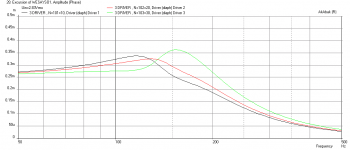
Here is a three chamber sim with ducts connecting the chambers and fs varies as specified above. Three drivers wired in series. I am not getting any wiggle even if I put some variation in the chamber volumes and characteristic lengths by up to 5%.
Freq response:
Impedance (zoomed in):
Cone displacement (note how different fs gives different behaviors):
Freq response:
Impedance (zoomed in):
Cone displacement (note how different fs gives different behaviors):
Attachments

Thanks X, that's quite clear... so the wiggle starts elsewhere. I'll look into it, just out of curiosity to find out what happens here.
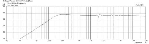
Today I took some time to see what caused the wiggle in the Impedance plot. Xrk971 had proved the peak is not dependant on the difference in drivers or their wiring.
After looking up the length corresponding to the double peak I got I got a suspicion the baffle might have something to do with it.
There were two peaks close to each other overlapping. One peak was at about 155.6 Hz, corresponding closely to the baffle length of 220,5 cm.
As you know there are two baffles bolted together with the speakers in-between. The back baffle has MLV glued to both sides. The speakers are thicker than the MLV around it. So I taped some neoprene to the inner edges of the front baffle to see what that would do.
Sure enough the peaks were a bit less, but still next to each other. After trying to put more tension on the bolts the ~155.5 Hz peak got higher and sharper. So that wasn't the cure. Originally I was going to put O-rings under the bolts, but due to making the baffle myself I decided to skip that part.
I just had to try what it would/could do so I put a rubber ring under half the bolts in the baffle. Bingo! Now there's only one big peak, aside from some noise on the graph. After putting the rubber rings under every bolt things didn't change much. Here's a graph of the results:

The rubber rings were made from the inner tube of a bicycle tire. So now my baffle looks like this:

I'll finish the second tower first and meanwhile figure out an elegant way to decouple the bolts. I was thinking heat shrink sleeves on the bolts might give the right results? Then again, maybe it isn't elastic enough. I could just revert back to the original plan of using O-rings... But then I have to cut some grooves in the recessed bolt holes.
After looking up the length corresponding to the double peak I got I got a suspicion the baffle might have something to do with it.
There were two peaks close to each other overlapping. One peak was at about 155.6 Hz, corresponding closely to the baffle length of 220,5 cm.
As you know there are two baffles bolted together with the speakers in-between. The back baffle has MLV glued to both sides. The speakers are thicker than the MLV around it. So I taped some neoprene to the inner edges of the front baffle to see what that would do.
Sure enough the peaks were a bit less, but still next to each other. After trying to put more tension on the bolts the ~155.5 Hz peak got higher and sharper. So that wasn't the cure. Originally I was going to put O-rings under the bolts, but due to making the baffle myself I decided to skip that part.
I just had to try what it would/could do so I put a rubber ring under half the bolts in the baffle. Bingo! Now there's only one big peak, aside from some noise on the graph. After putting the rubber rings under every bolt things didn't change much. Here's a graph of the results:
The rubber rings were made from the inner tube of a bicycle tire. So now my baffle looks like this:
I'll finish the second tower first and meanwhile figure out an elegant way to decouple the bolts. I was thinking heat shrink sleeves on the bolts might give the right results? Then again, maybe it isn't elastic enough. I could just revert back to the original plan of using O-rings...
But then I have to cut some grooves in the recessed bolt holes.
Last edited:
Interesting. It suggests a plate resonance in the baffle. It is a giant vibraphone bar after all... 😉
I'd think you'd be able to find some flat rubber washers of appropriate size available somewhere. I can't see any advantage to using an O ring.
I'd think you'd be able to find some flat rubber washers of appropriate size available somewhere. I can't see any advantage to using an O ring.
Good discovery , maybe stupid but is it possible the rubber seal some air pressure/vacuum from behind driver leaking thru bolt hole, know this possibility depend how 2 x baffle connected and holes is executed.
Hi wes.
try sourcing out platic or rubber washers used when mounting glass doors on furniture.
Might find the right size.
Danny
try sourcing out platic or rubber washers used when mounting glass doors on furniture.
Might find the right size.
Danny
Today I took some time to see what caused the wiggle in the Impedance plot. Xrk971 had proved the peak is not dependant on the difference in drivers or their wiring.
After looking up the length corresponding to the double peak I got I got a suspicion the baffle might have something to do with it.
There were two peaks close to each other overlapping. One peak was at about 155.6 Hz, corresponding closely to the baffle length of 220,5 cm.
As you know there are two baffles bolted together with the speakers in-between. The back baffle has MLV glued to both sides. The speakers are thicker than the MLV around it. So I taped some neoprene to the inner edges of the front baffle to see what that would do.
Sure enough the peaks were a bit less, but still next to each other. After trying to put more tension on the bolts the ~155.5 Hz peak got higher and sharper. So that wasn't the cure. Originally I was going to put O-rings under the bolts, but due to making the baffle myself I decided to skip that part.
I just had to try what it would/could do so I put a rubber ring under half the bolts in the baffle. Bingo! Now there's only one big peak, aside from some noise on the graph. After putting the rubber rings under every bolt things didn't change much. Here's a graph of the results:
The rubber rings were made from the inner tube of a bicycle tire. So now my baffle looks like this:
I'll finish the second tower first and meanwhile figure out an elegant way to decouple the bolts. I was thinking heat shrink sleeves on the bolts might give the right results? Then again, maybe it isn't elastic enough. I could just revert back to the original plan of using O-rings...
Great detective work there! I think I have an elegant solution for you: Parker Sta-o-seals. They look like a metal washer but have an elastomeric o-ring bonded to them. Designed for high pressure bolt seals, but I think should decouple your plates and be invisible. Looks like a small flat washer.
http://www.allsealsinc.com/statoseals.pdf
An externally hosted image should be here but it was not working when we last tested it.
The trouble I see with a flat washer, even a rubber one, under a flathead screw, is that it's going to have to deform a lot to fit into that conical space. You could use a socket head screw instead, but then you've got a lot of re-machining to do to make the bottom of the bolt recess flat. I think maybe the O-ring is not a bad idea, and I'd question whether you need to machine any recess for it. Maybe better to let it find its place between the screw and the countersink. Then again, your inner tube washers could work well too; just need to trim them nicely. Hope some of this makes sense; it's been a long day...
Last edited:
You may need to counterbore all the conical holes and use a square boss socket cap screw. The statoseal will sit flush in the C-bore hole.
Thanks for the suggestions...
I'm in the process to order neoprene rubber M6 washers 1mm thick. They compress nicely and should do the job. I tested that with the neoprene seal (also 1mm thickness) I have. They should be able to fit nicely and compress to the cone shape without problem.
They come with an adhesive backing.
BYRTT: The first (back) baffle should seal off all holes with a neoprene seal (on top of the MLV) to the enclosure.
My front baffle is only 6 mm thick so potholes are out of the question.
If this doesn't work out I'll just cut some more tube 😀.
Last edited:
- Home
- Loudspeakers
- Full Range
- The making of: The Two Towers (a 25 driver Full Range line array)