Best example is Neurochrome 186 which uses LM3886 chip amp plus several op amps - but its priced a little high. In the headphone amplifier forum there are people looking at multiple op amps in parallel - up to 32 - to get a simple, low cost design with very low distortion. Now if we could get someone with actual amplifier design DIY experience to develop something to suit this application...
Same boat here. NC, what is your definition of low power?
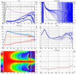
Here's all boards in one plot:
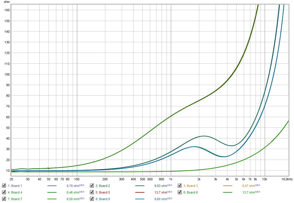
As seen, the second board i finished today is ever so slightly different from the first. As I had already done separate cap measurements this didn't come as a surprise. I won't worry about it though. I'm not using these boards to shape an overall crossover or end result. This difference will get lost within the total DSP correction and would be very hard to find in the overall results.
It may be about a ~ 0.5 uF difference overall or something close to that, but I don't have spare capacitors laying around to make up for that. The ones I do have, all are way too big a value to be of use.
Attachments
You would need an array of amps. I have a 4x140W Pascal module based amp on order from VTV Amplifiers but I have also been looking into amplifier architecture for something suitable for lots of low power channels with good fidelity. The answer seems to be a composite amplifier using error correction to drive the nonlinear distortions down an order of magnitude below what you get without the global feed back loop. Best example is Neurochrome 186 which uses LM3886 chip amp plus several op amps - but its priced a little high. In the headphone amplifier forum there are people looking at multiple op amps in parallel - up to 32 - to get a simple, low cost design with very low distortion. Now if we could get someone with actual amplifier design DIY experience to develop something to suit this application...
What would you call a Stereo amplifier with 12 output mosfets per side?
Certainly not low power, but quite entertaining! 😉
Same boat here. NC, what is your definition of low power?
something on the order of 10-20W peak
even with 4 or more drivers in series parallel, arrays don't even need that much except where boosting the low end
the Z makes a big difference as 16 or 32 ohms is a lot easier for a scaled up headphone driver than 4 ohms
back breaking!What would you call a Stereo amplifier with 12 output mosfets per side?
😉
I'm terrible, I know, but we're talking about high resolution solutions here, right? 😛
I went back into the garage, remembering I did have a few spare capacitors (Jantzen cross caps) that I removed from my conjugation network, the high frequency correction part. Those parts were made up of real small values so I took a gamble and...
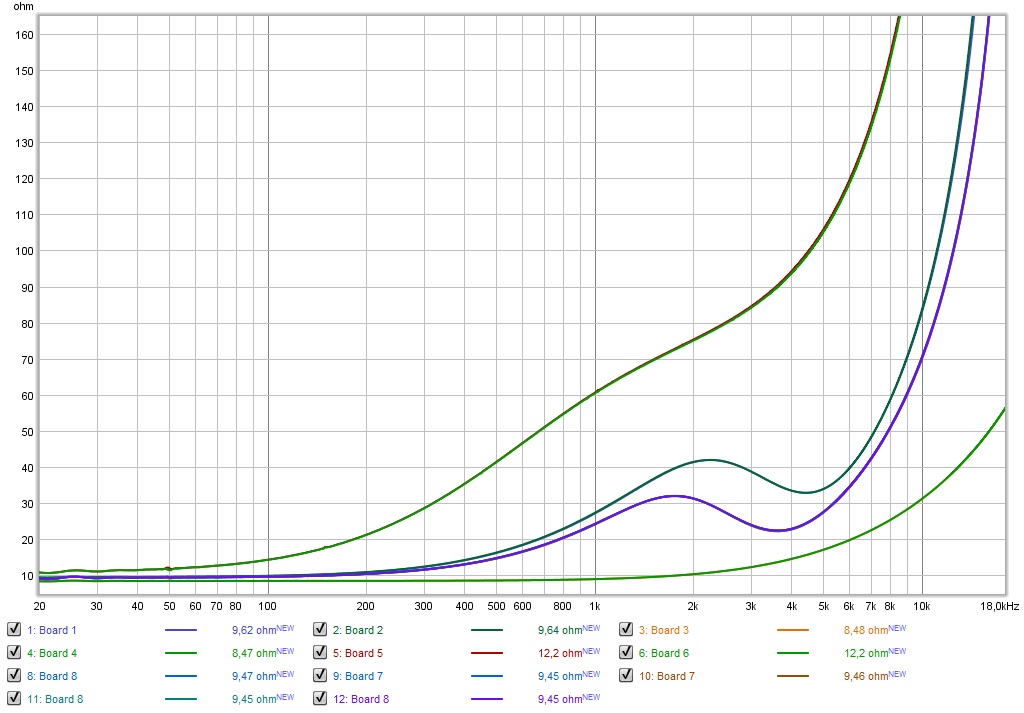
There are 2 measurements of board 7 and two of board 8, but now they measure as one! The Jantzen cross cap is a tiny size, so it won't affect anything else. So I'd say all boards are well within tolerable limits now. 😀
I went back into the garage, remembering I did have a few spare capacitors (Jantzen cross caps) that I removed from my conjugation network, the high frequency correction part. Those parts were made up of real small values so I took a gamble and...
There are 2 measurements of board 7 and two of board 8, but now they measure as one! The Jantzen cross cap is a tiny size, so it won't affect anything else. So I'd say all boards are well within tolerable limits now. 😀
Attachments
So I just did a quick sim of flanking the central 8 drivers of a line array flanked by columns of 8 low pass filtered drivers and tuned the amplitude, delay, and low pass cut off for the best horizontal response. This is kind of Tektonish.
I was able to narrow the horizontal response from 500 Hz up to where it met up with natural narrowing due to driver beaming at HF. Not perfectly uniform horizontal but really reduced the front and sidewall reflections. Just a start at this kind of thing. It would be simple to sim the original Tekton array in Vituix but I left that for later.
You could get this narrowing also going OB but then you loss bass. This way the additional drivers add bass response. Good to use a driver like TC9 that isn't too expensive...
If you look at the plot I posted earlier, the line of TC9's, with the shading scheme, only has a small area where floor and ceiling still have quite the influence. Caused by those ceiling spraying lobes.
(ceiling lobes having an effect from about ~5 KHz to 10 KHZ...)
If we could have a small array to do the top end, eliminating those lobes (like bbutterfield showed in his fractal array: Fractal Array Straight CBT with Passive XOs and no EQ) but keep a large number of output drivers as to not loose the dynamics and SPL capability that's so much fun about the array, you'd have a very good solution.
I would not want to go as far as to control the horizontal output as well, as that's what my damping panels at first reflection points should solve for the most part. You could, sure... making it act like the Lexicon or Beolab 90. Might as well make it user adjustable and yes, you'd need a lot of amplifiers. Something like the Beolab 90 has 14 B&O ICEpower AM300-X, with a max of 8,200 total watts of musical power. So those are not low power. 😱
Last edited:
we are looking for increased vertical directivity in the 5-10 khz region which is where the individual driver directivity is just beginning to narrow. The Tekton array does that - except that it becomes too narrow. I will post some charts on my thread later, hopefully later today. I think the (only) way to avoid the floor and ceiling splash effects without giving up seated plus standing listening is with carpets and acoustic ceiling tiles.
I'd settle for avoiding the lobes and have excellent seated performance and slightly less standing up, but at least balanced. I've seen that kind of directivity in plots from a tall ribbon, I'd basically try to keep that from 5 KHz upward. That probably takes a little interference to make it happen, as did my current schematic, to keep an even frequency output over a wide area. Get rid of the lobes due to driver spacing while keeping output capacity is all you'd need to get a better performance of the top end.
I'll never put up damping on the ceiling or rugs on the floor to remedy this. I have a house from 1927 and I am restoring the ceiling back to what it looked like (though with different materials) when it was build. Out with the metal ceiling (which was dreadful in measurements) and damping between upstairs floor and new ceiling. (very basic, but sleek appearance)
All this is dreaming though, as I'm quite comfortable with what I have now and the current tweaks should up that scale even more. 🙂
Last edited:
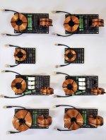
I did try hard to make them "well done". 🙂
All components have a layer of either a flexible glue underneath or double sided (high temp resistant) tape. Plus tie-wraps to secure them and the coils as far apart as possible plus alternated in direction according to the test done by Troels.
I did notice a lot of crossover boards I found online that looked quite nice but had coils mounted quite close together, even with high priced foil air coils. I tried to keep it reasonable. Would it be a reason the potted components from Duelund have such a stellar reputation?
I noticed differences in impedance tests on a laptop with battery power vs powered by the net. Ideally you'd mount them vibration free in separate enclosures I suppose 😀.
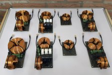
Another view... as they will be hidden from sight soon enough!
Attachments
Last edited:
posted tekton array response in this thread
https://www.diyaudio.com/forums/multi-way/336743-help-understanding-tekton-tweeter-array-schematic-6.html#post6295862
https://www.diyaudio.com/forums/multi-way/336743-help-understanding-tekton-tweeter-array-schematic-6.html#post6295862
I did notice that, quite promising!
I'd like to try it with even smaller tweeters like the Vifa XT19, as said, horizontal it should transfer seamlessly to the TC9 array, and vertically remove the lobing and have a reasonable output. All of it fitting the size of one TC9 😱.
I'd like to try it with even smaller tweeters like the Vifa XT19, as said, horizontal it should transfer seamlessly to the TC9 array, and vertically remove the lobing and have a reasonable output. All of it fitting the size of one TC9 😱.
VituixCAD said:Feature additions and bug fixes for different builds of VituixCAD version 2
2.0.53.0 (2020-07-31)
Main
Fixed response interpolation within axial and the smallest measured vertical off-axis angle.
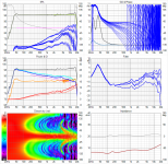
An upgrade in outcome without having to do anything. Results are even better than previously anticipated:
Just had to re-run the EQ...
(got to look closely, but the differences did make me 🙂)
Previous version of VituixCad looked like this:
Attachments
I did notice that, quite promising!
I'd like to try it with even smaller tweeters like the Vifa XT19, as said, horizontal it should transfer seamlessly to the TC9 array, and vertically remove the lobing and have a reasonable output. All of it fitting the size of one TC9 😱.
This one: https://www.hifisound.de/out/media/pdf.php?r=bcP13qKCOKpXXEwshNHuLpC1F%2F8vmPBuBgMv1fGAjts5Pjhl6Sb%2Bj7aEmt5wE2zykZ3pkUiHx8QwzsRzU8lCEw%3D%3D.pdf
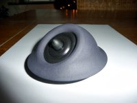
I agree, it is quite small and it can be removed from it's face plate, making it possible to 3D print (SLS print, not filament based) a new one that could incorporate all of them (you could even experiment with different waveguide properties).
It's the little brother of the XT25 SC, which I liked very much and have designed some different faceplates for.
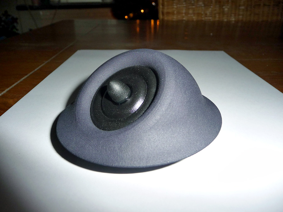
It's the little brother of the XT25 SC, which I liked very much and have designed some different faceplates for.
Attachments
- Home
- Loudspeakers
- Full Range
- The making of: The Two Towers (a 25 driver Full Range line array)