I opened my Douglas Self Small Signal Audio Design book this morning and found a chapter on capacitor distortion of all things. Non-electrolytic caps can distort measurably. Self tests caps by running a THD sweep on a simple RC low pass filter (series 1K R, cap to gnd). 3rd harmonic distortion at level of .002% with 15 Vrms on a 220 nf polyester cap was measured, for example. That isn't really a lot unless your target for a preamp that uses that cap is even lower distortion. Polypropylene and polystyrene caps measured lower by an order of magnitude. Distortion rises with frequency from these levels starting at around 1 khz.
As I wait for the order to be corrected I'm still thinking about that bypass cap (lol).
If it were true that the combined caps make up a better functioning "joint" cap I would have no problem adding a Vishay 0.01uF to the 'bigger' ClarityCaps.
I had hoped to read more point of views on that 🙂. It costs nothing extra as the parts are here, but as said, I'm not taking the arrays apart again to remove or add something like that, once it is in there.
People that hear the differences are shunned by the popular kids so many won’t say anything on the record.....if it makes you feel any better about doing it; I’ve never had it sound worse by adding a bypass cap, just some add more detail than others. I never used the 1837 but heard it’s one of the better ones. Even though you say it’s a different application isn’t the theory still the same?
Last edited:
That may be a valid criticism of the paragraphs I quoted but there is meat in the rest of the article.
I retrospect, I think the 200 khz -3db bandwidth target is a subtle dig at class D. Not even Purifi, gets anywhere close to that,or tries to. Perhaps this will happen when switching frequencies are extended to 2 Mhz or so. One wonders why such high bandwidth is pursued, unless the goal is to pass 20 khz squarewaves or cater to the same community that places value in tweeters whose response extends well beyond 20 khz.
I think the answer as to why 200Khz BW is pretty simple. Its an unintended side effect of having negligible loss and phase shift over the audio bandwidth.
Think of the amp as being a unity gain low pass filter and look at the magnitude and phase at 20 khz.
-3db at 200 khz => -.04 db at 20 khz and 3 deg phase shift
-3 db at 100 khz => -.16 db at 20 khz and 12 deg phase shift
but class today seldom gets > 50 khz -3db BW
-3 db at 50 khz 1st order filter => -.85 db at 20 khz
but class d not first order roll off
if 50 khz 2nd order -3db at 50 khz => -.1 db at 20 khz and 10 deg phase shift
RE the bypass caps.
A small cap in parallel with a larger cap (at least on board level design) as NC535 pointed out is to make sure the cap remains a cap at all operation levels.
When a cap is used, depending on the material, the capacitance can change a lot over, DC bias and temperature. Putting caps in parallel also lowers the esr but creates some anti-resonances in the extreme high frequencies.
Not sure what that translates into the audible domain. Might depend on equipment used, cap material and crossover layout. I haven't done any bench tests of large through-hole components.
People that hear the differences are shunned by the popular kids so many won’t say anything on the record.....if it makes you feel any better about doing it; I’ve never had it sound worse by adding a bypass cap, just some add more detail than others. I never used the 1837 but heard it’s one of the better ones. Even though you say it’s a different application isn’t the theory still the same?
RE the bypass caps.
A small cap in parallel with a larger cap (at least on board level design) as NC535 pointed out is to make sure the cap remains a cap at all operation levels.
When a cap is used, depending on the material, the capacitance can change a lot over, DC bias and temperature. Putting caps in parallel also lowers the esr but creates some anti-resonances in the extreme high frequencies.
Not sure what that translates into the audible domain. Might depend on equipment used, cap material and crossover layout. I haven't done any bench tests of large through-hole components.
Even though it's often frowned upon from a technical point of view (for audio frequencies) the multitude of positive reports from a small bypass cap are there too. If it can't really hurt, I might as well put a small vishay in parallel to the ClarityCaps.
In the past I have even heard differences between JRiver releases. That had me stunned and a couple of JRiver updates later all was well again. I though it was just me, until BYRTT reported the same effect.
I don't think it will actually hurt anything, and who knows, maybe those positive reports on the Vishay MKP1837 are really worth something. We're not talking about expensive boutique caps here.
I think the answer as to why 200Khz BW is pretty simple. Its an unintended side effect of having negligible loss and phase shift over the audio bandwidth.
Think of the amp as being a unity gain low pass filter and look at the magnitude and phase at 20 khz.
-3db at 200 khz => -.04 db at 20 khz and 3 deg phase shift
-3 db at 100 khz => -.16 db at 20 khz and 12 deg phase shift
but class today seldom gets > 50 khz -3db BW
-3 db at 50 khz 1st order filter => -.85 db at 20 khz
but class d not first order roll off
if 50 khz 2nd order -3db at 50 khz => -.1 db at 20 khz and 10 deg phase shift
Indeed that may make sense, but the same can be true with DAC's and the way they filter the audible bandwidth...
Even though it's often frowned upon from a technical point of view (for audio frequencies) the multitude of positive reports from a small bypass cap are there too. If it can't really hurt, I might as well put a small vishay in parallel to the ClarityCaps.
Let me clarify. There are differences when caps are put in parallel that are greater than just an increase in capacitance. For example, in the case of loudspeakers the parallel combo will have lower esr (among other things) than the single. At least there are some physical differences that can explain why there might be an audible difference. If one were to take it to an extreme, a cap that has a large esr bypassed by a vanishing low esr cap would have an increase in treble level all other factors being equal. Would that level be enough to be audible? This is where I have no experience but as you know just because a large number of people say it is so does not make it objectively true🙂.
but all such effects should show up in either Z or FR or THD sweeps.
As a practical matter though its simpler just to throw in the cap and be done with it. the scientist in me would want to do a double blind listening test with cap in vs out.
As a practical matter though its simpler just to throw in the cap and be done with it. the scientist in me would want to do a double blind listening test with cap in vs out.
but all such effects should show up in either Z or FR or THD sweeps.
As a practical matter though its simpler just to throw in the cap and be done with it. the scientist in me would want to do a double blind listening test with cap in vs out.
Agreed! The example I gave only outlined 1 possible example of 1 extreme parameter of the parallel combo. I've did not intend to show/explain that variable was "the" variable that has people reporting improvements as I don't know the exact answer 🙂, only that there are physical differences for Caps in parallel other than an increase in capacitance.
Question, do all these reports of a"audible improvement" show ZERO change in Z or FR or THD sweeps or CSD?
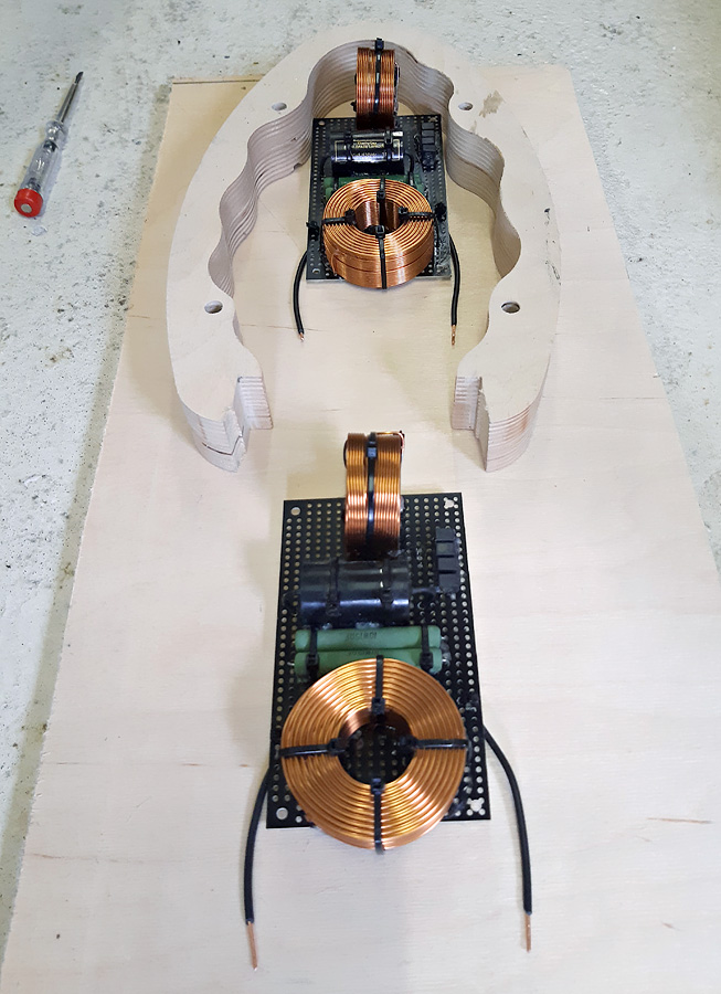
Okay, I have wired one board and measured it with an 8.2 Ohm resistor I had, after which I added the Vishay MKP1837 0.01uF and measured it again.
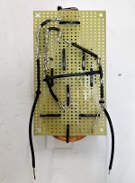
The board:
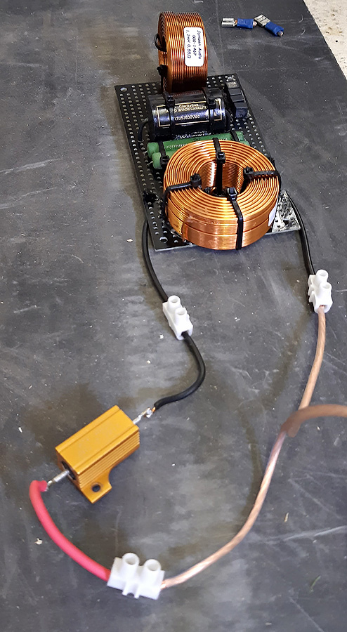
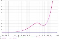
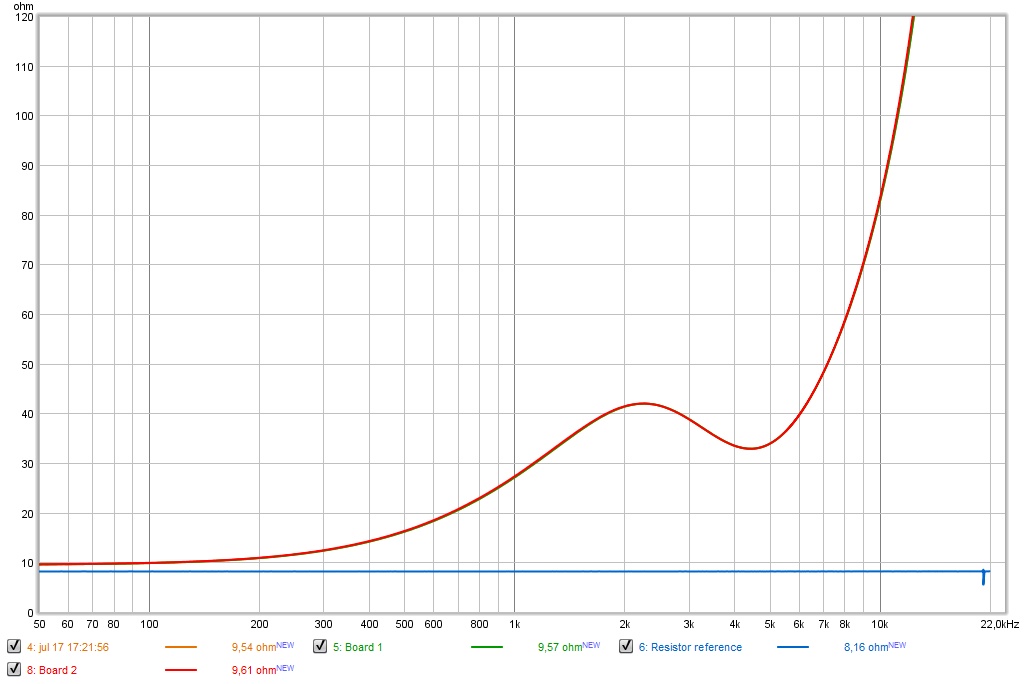
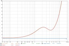
The results, together with an exported sim from X-Sim:
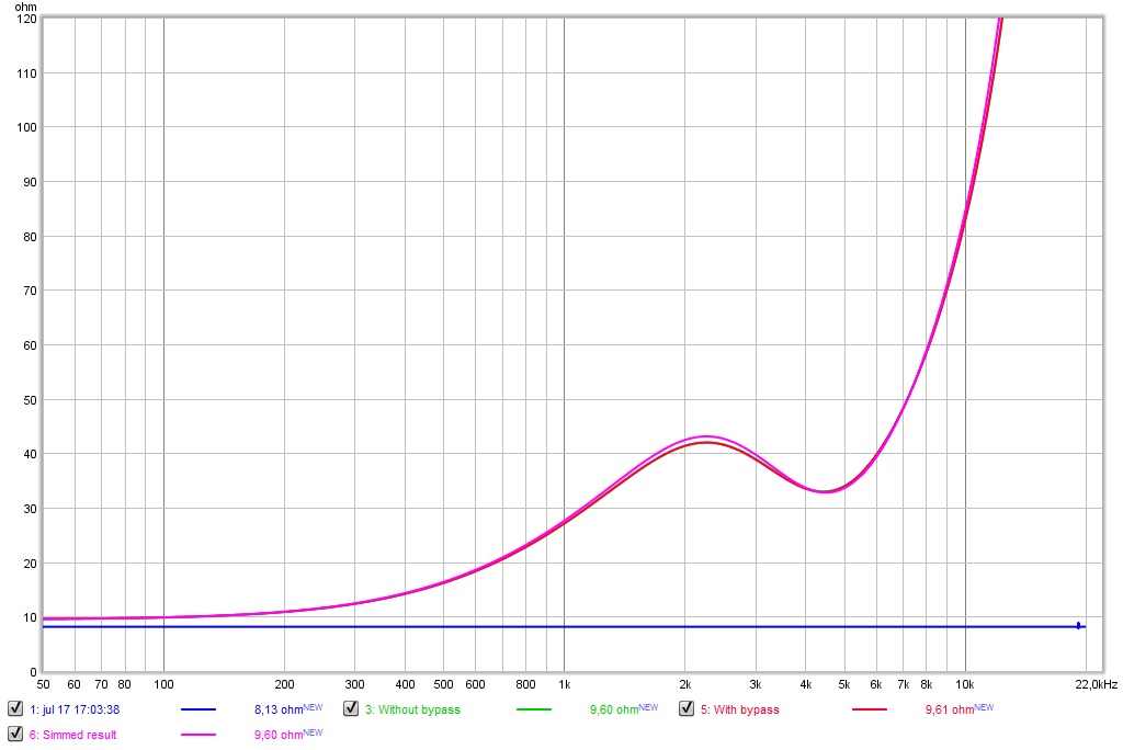
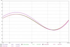
And a more detailed look at the part where the frequency is boosted a little by the cap(s):
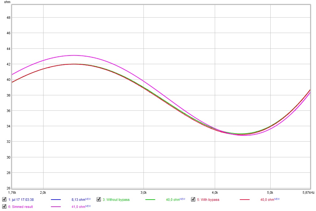
As can be seen, the impedance measurement with the Vishay dips slightly lower. However there's another deviation from the sim that's larger than this slight difference, and that seems to be either the value of the bigger 2.7 mH coil or the resistor.
Simming it with a 29 ohm resistor (about 3% lower than it's 30 Ohm value) looks like this:
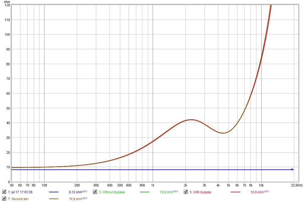
So, there's no definitive answer to the bypass cap's functionality, but it does seem all components are quite close within their tolerances.
I'll let the bypass cap stay, I see no immediate reason to choose otherwise. This board seems to be pretty much spot on target, considering component tolerances. If all other boards turn out equally close to their simulated values I'll be a happy man.
On to the next one I guess...
The board:
The results, together with an exported sim from X-Sim:
And a more detailed look at the part where the frequency is boosted a little by the cap(s):
As can be seen, the impedance measurement with the Vishay dips slightly lower. However there's another deviation from the sim that's larger than this slight difference, and that seems to be either the value of the bigger 2.7 mH coil or the resistor.
Simming it with a 29 ohm resistor (about 3% lower than it's 30 Ohm value) looks like this:
So, there's no definitive answer to the bypass cap's functionality, but it does seem all components are quite close within their tolerances.
I'll let the bypass cap stay, I see no immediate reason to choose otherwise. This board seems to be pretty much spot on target, considering component tolerances. If all other boards turn out equally close to their simulated values I'll be a happy man.
On to the next one I guess...
Attachments

Last edited:
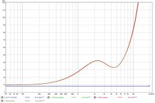
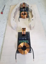
Next in line, board no. 2, the copy for the other side.
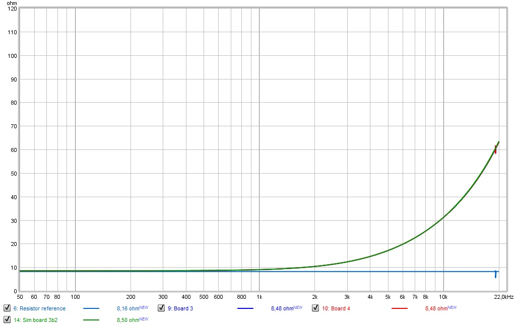
And a measurement of it,
So far I'm impressed with the results, spot on! They are essentially the same in an impedance measurement.
And I'm not kidding about that, here's both zoomed in pretty far:
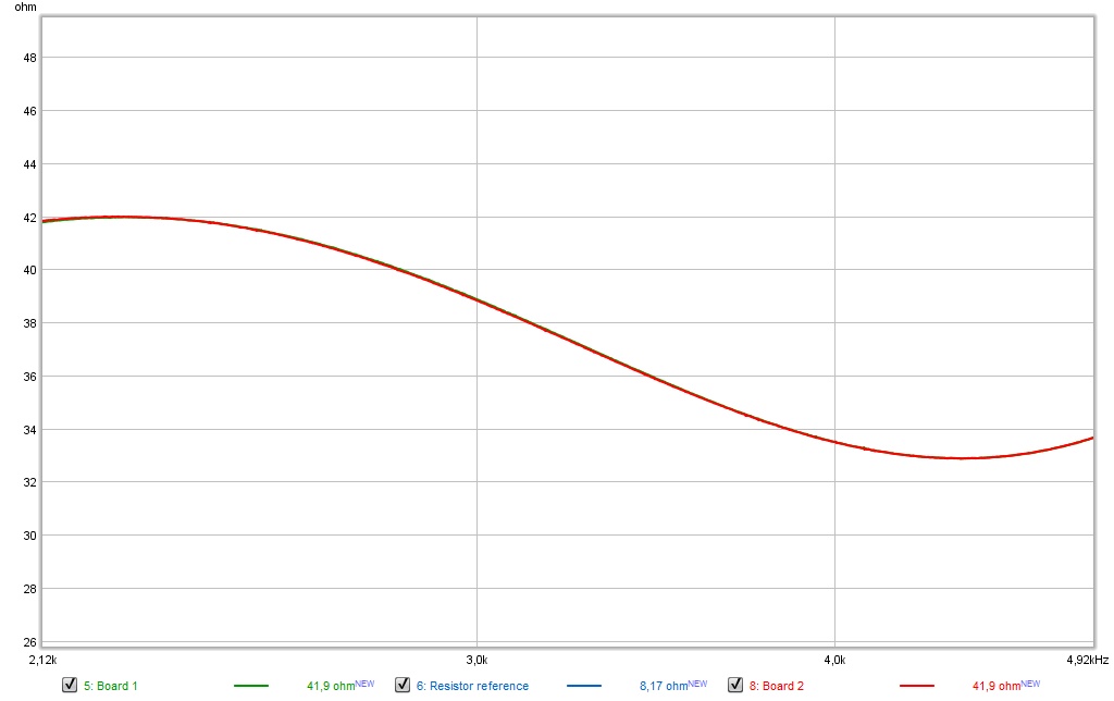
Not bad eh? 🙂 You can just about make out a faint green trace below the red one...
And a measurement of it,
So far I'm impressed with the results, spot on! They are essentially the same in an impedance measurement.
And I'm not kidding about that, here's both zoomed in pretty far:
Not bad eh? 🙂 You can just about make out a faint green trace below the red one...
Attachments

Board 3 and 4, the simple ones...
In a sim (X_Sim) a value of 0.470 mH is pretty much spot on, the caps both act as ~0.008 uF so again a small deviation, both boards are measuring the same though. 🙂
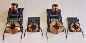
Production thus far:
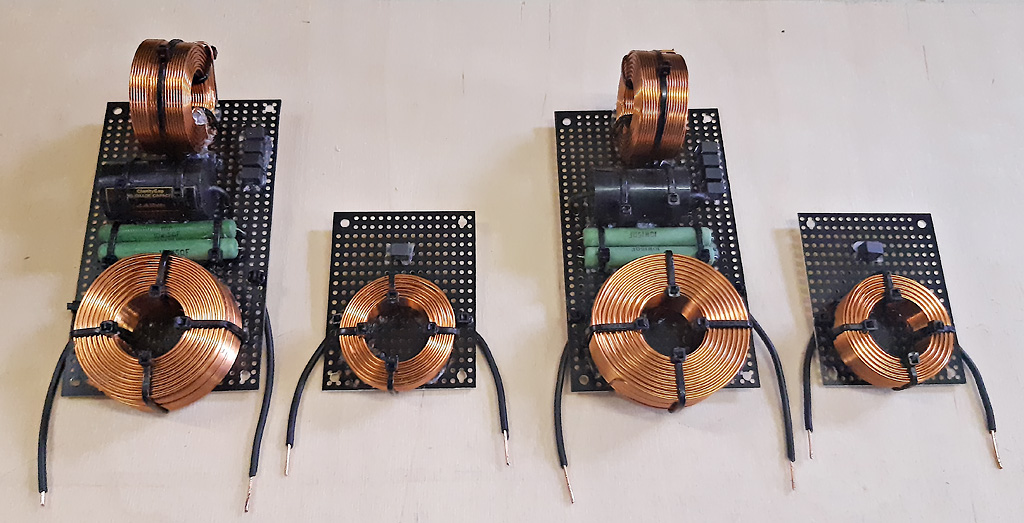
I can make two more boards with what I have on hand. Sadly the store I ordered from is closed for another few weeks so I can't get my order fixed until the 29th. Here's to hoping the last four boards will turn out as close as these 4 are.
All in all I'm pretty happy so far. I have no real experience building crossovers so I took my queues from Troels and Tony Gee.
And the handy tip from fluid about cutting the boards. 😉 I used my Dremel with a cheap set of Diamond cutting disks (sourced from Amazon) and cut them by clamping the Dremel to my table and having a side bar from a few pieces of wood for guidance. The cutting disk went through it like butter. I have 20, still using the first one and all cutting is done already.
In a sim (X_Sim) a value of 0.470 mH is pretty much spot on, the caps both act as ~0.008 uF so again a small deviation, both boards are measuring the same though. 🙂
Production thus far:
I can make two more boards with what I have on hand. Sadly the store I ordered from is closed for another few weeks so I can't get my order fixed until the 29th. Here's to hoping the last four boards will turn out as close as these 4 are.
All in all I'm pretty happy so far. I have no real experience building crossovers so I took my queues from Troels and Tony Gee.
And the handy tip from fluid about cutting the boards. 😉 I used my Dremel with a cheap set of Diamond cutting disks (sourced from Amazon) and cut them by clamping the Dremel to my table and having a side bar from a few pieces of wood for guidance. The cutting disk went through it like butter. I have 20, still using the first one and all cutting is done already.
Attachments
Last edited:
That's the idea, I want to mount them with Torx wood screws and rubber rings between the board and the enclosure, hence the test fit in the enclosure profile above.
Even though I mentioned the deviation, it could very well be outside of the measurement setup accuracy.
In fact I would think that's even more likely than the Vishay being (far) outside of its tolerance. The tolerance on the Vishay is 1% if I look it up online. All other caps seemed to have a similar deviation on the top end. Anyway, for my purpose it's well within an acceptable range.
Last edited:
The accuracy of the impedance jig relies heavily on how accurately you can measure the resistance you are using. Should be good for relative measurements as it is all being measured the same way.
I know its probably explained previously, but how many other changes are you making besides the bypass caps?
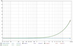
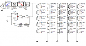
Up until now I've had the 25 drivers in each array run full range. Like in this schematic:
That leads to this prediction in simulation after DSP correction:

The boards I'm making should have an advantage over the above, by having slightly less deviation moving up and down in the sweet spot. The top end is more balanced and way less peaky outside of the corrected window.
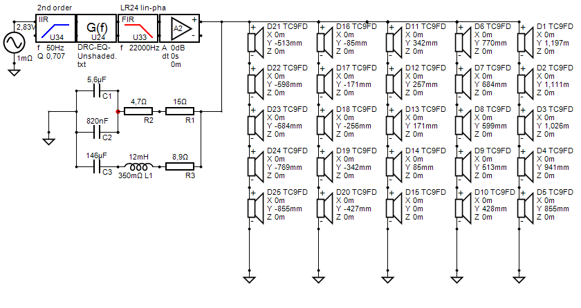
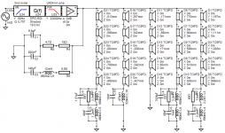
The schematic I am building:
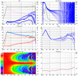
And the prediction that follows (again after applying DSP):

If you look at the vertical window it should be clear that the frequency shading that is applied manages to focus the vertical window over the entire range of interest. This should create a wide enough sweet spot in all directions and keeps a reasonable (a bit more dark) performance standing up.
Look at the orange line in the left-middle graph as the predicted in-room result. That's what these boards are for, creating a slight advantage overall but an even more clear advantage at high frequencies. The red line is showing the Directivity Index.
This should make it easier for me to use a single point measurement for DSP correction while keeping a good performance around that single point. All in theory of course, we'll have to wait and see if it is an audible improvement. The correction file has less wiggles and this is my queue that overall this result should be worth the experiment.
There's still 5 drivers running full range, around those 5 drivers the top end is gradually shaded in each successive group. This keeps the dynamics of the array in tact while (hopefully) clearing up the top end and having an advantage for "in room" reflections from floor and ceiling vs the unshaded array.
That leads to this prediction in simulation after DSP correction:
The boards I'm making should have an advantage over the above, by having slightly less deviation moving up and down in the sweet spot. The top end is more balanced and way less peaky outside of the corrected window.
The schematic I am building:
And the prediction that follows (again after applying DSP):
If you look at the vertical window it should be clear that the frequency shading that is applied manages to focus the vertical window over the entire range of interest. This should create a wide enough sweet spot in all directions and keeps a reasonable (a bit more dark) performance standing up.
Look at the orange line in the left-middle graph as the predicted in-room result. That's what these boards are for, creating a slight advantage overall but an even more clear advantage at high frequencies. The red line is showing the Directivity Index.
This should make it easier for me to use a single point measurement for DSP correction while keeping a good performance around that single point. All in theory of course, we'll have to wait and see if it is an audible improvement. The correction file has less wiggles and this is my queue that overall this result should be worth the experiment.
There's still 5 drivers running full range, around those 5 drivers the top end is gradually shaded in each successive group. This keeps the dynamics of the array in tact while (hopefully) clearing up the top end and having an advantage for "in room" reflections from floor and ceiling vs the unshaded array.
Attachments


Last edited:
Thanks for the details, I’ve never heard a floor to ceiling line array but never would have guessed they had such narrow vertical dispersion issues!
So that stops my wondering if you’d be able to pinpoint any improvement towards the bypass caps but I suppose if it does sound better it’s overall a win.
So that stops my wondering if you’d be able to pinpoint any improvement towards the bypass caps but I suppose if it does sound better it’s overall a win.
- Home
- Loudspeakers
- Full Range
- The making of: The Two Towers (a 25 driver Full Range line array)