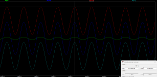

Example for bootstrapping according to the example in the document. the voltage gain is just 2 /6dB. the input voltage is 23Vpeak !
you can see the Vin about 23Vp (46Vpp) and the Vout is about 46Vp (92Vpp).
rail is realistic with 56V from a 40VAC transformer gives about 56Volt at the rails. a changed the BJT transistors to something in the model database with 80Vce.

ps: i played around with bigger gain but this is not working - gain 2 /6dB seams to be good. otherwise the Vout sticks to the V+ rail !!!
kr
chris
you can see the Vin about 23Vp (46Vpp) and the Vout is about 46Vp (92Vpp).
rail is realistic with 56V from a 40VAC transformer gives about 56Volt at the rails. a changed the BJT transistors to something in the model database with 80Vce.
ps: i played around with bigger gain but this is not working - gain 2 /6dB seams to be good. otherwise the Vout sticks to the V+ rail !!!
kr
chris
Put in a mica 22pF parallel to Rfb2
No oscillations!
To play with supply voltage I insert Nichicon UKT35V
workbench power supply in serial mode can only do +-30V


No oscillations!
To play with supply voltage I insert Nichicon UKT35V
workbench power supply in serial mode can only do +-30V
Last edited:
@ DAN yes, look on heatsink MFB-mixed feedback
first Test with OPA551 in M2OPS original mode-no opamp limiting --MFB
Rails +-24V--Vin 220mVrms-- Vout2,83Vrms--on Gate 8,77Vpp swing(divided 2, --4,38V on Gate of MOSFET)
clipping Limit Vin 900mVrms--11,64mVrms-- on gate 35,54Vpp swing--on Gate 17,77V
Rails +-26V--clipping Limit Vin 900mVrms--11,64Vrms-- on gate 35,54Vpp swing--on Gate 17,77V
Rails +-28V--clipping Limit Vin 1Vrms--12,92mrms (20,86W/8R)-- on gate 39,3Vpp swing--on Gate 19,65V
Rails +-30V--clipping Limit Vin 1,1Vrms--14,24Vrms (25,34W/8R)-- on gate 43,3Vpp swing--on Gate 21,65V
------------------------------------------------------------------------------------------------------------------------
test with bootstrap opamp604-----fg=143kHz
Rails +-24V--Vin 220mVrms-- Vout2,83Vrms--on Gate 8,77Vpp swing (divided 2, --4,38V on Gate of MOSFET)
clipping Limit Vin 800mVrms--10,34Vrms(13,36W/8R)-- on gate 31,46Vpp swing--on Gate 15,73V--Limited due zener diode 15V
tested with +-26V,28V and 30V NO change in fg but also in Max power and voltage swing.
after longer testing temp goes up on the MOSFET and clipping limit goes down to ~740mV -Vin--heatsink too small
-clipping Limit Vin 740mVrms--Vout 9,53Vrms (11,35W/8R)-- on gate 28,96Vpp swing--on Gate 14,48V
Last edited:
Hi
the last simulation, but with the OPS included, i guess i am stupid. i do not understand the circuit.
i played around and finally i got a realistic version of a bootstrapping version. i changed the BJT transistors to 120V and keep the rails at 56V. i played around with this circuit and set the RFb, Rfb1 to a gain of 15dB. so you need an input voltage of 4V peak to get the maximum out. the swing is 22,75 Vpeak -- not bad for an opamp with can just handle 15V rail.
as i wrote above ....i am not able to set the Rfb, Rfb1 this way to get more out....
it is your turn ...ladies / gentlemen 😉
kr
chris
Attachments
Last edited:

Oh ..Hi Mark JohnsonLT1010 is from the previous century.
_
thank you
LT1010 is just the place holder for the Mosfet OPS with the correct fb...R3,R4
kr chris
Any ideas why R3 and R4 are the values that they are in the Spice model?
Last edited by a moderator:
Bootstrap boards have arrived, nicely edge profiled as seen up thread.
I'm looking to achieve a 50W M2OPS with an OPA828 on the front end, likely with mixed feedback. Is this possible with 32V?
First stage will be to get the Bootstrap boards and OPA828 working properly with the 24V amp back end.
I'm concerned about the OpAmp latching/ going unstable on startup, perhaps speaker protection might be a wise addition.
No, opa828 has a recommended Supply +- 18V and according datasheet fig. 6-18, fig. 6-19 max output swing is +-13V.
So again, if you, like me, prefere the sound of opa828, you have to do it like thread #297 with 24V and this LM329 (kill +-6,9V).
Or install a 400VA/15VAC tranformer and serve all parts with +-18V supply and increase idle current for 4 ohm speakers. dont go over 36W power loss on MOSFET.
If you have 8R speaker you have to increase Voltage, so the opa551 or opa445 can handle more supply voltage, and therefore more opamap output swing is possible and more on the MOSFET gates.....but look a heat on MOSFET more voltage means reduce idle current in class A, dont go over 36W power loss on MOSFET.
opa445
with +-24V (NO LM329) clipping Limit Vin 830mVrms--Vout 10,70Vrms (14,31W/8R)-- on gate 33,60Vpp swing--on Gate 16,80V max
with +-30V (NO LM329) clipping Limit Vin 1,1Vrms--Vout 14,23Vrms (25,31W/8R)-- on gate 43,23Vpp swing--on Gate 21,6Vmax
my workbench supply is limited in serial mode to +-30V...I cant do more....
opa828 with bootstrap pcb (zener 15V)
with +-24V clipping Limit Vin 800mVrms--Vout 10,35Vrms (10,35W/8R)-- on gate 31,53Vpp swing--on Gate 15,765V max.
regards
Harry
F5Pi is designed for +/- 24V rails and pure Class A.
www.diyaudio.com/community/threads/all-hitachi-lateral-fet-amplifier-for-diy-described-by-paul-kemble.220923/
Patrick
www.diyaudio.com/community/threads/all-hitachi-lateral-fet-amplifier-for-diy-described-by-paul-kemble.220923/
Patrick
Last edited:
Not sure.No, opa828 has a recommended Supply +- 18V and according datasheet fig. 6-18, fig. 6-19 max output swing is +-13V.
So again, if you, like me, prefere the sound of opa828, you have to do it like thread #297 with 24V and this LM329 (kill +-6,9V)
The opa828 will tolerate up to 40v of voltage difference across its inputs, this can be -1v on one pin and +39 on the other.
My understanding is that the Bootstrap circuit works by oscillating the supply voltage which the opAmp sees, this is what gives it the increased output and allows the opAmp to tolerate the higher rail voltage.
I've got a 604 front ended amp that works well. I know that the opa828 is better, if I can get more power at the same time without an increase in distortion then that would be great.
There's nothing new here. Shame that those who have gone before are keeping quiet.
Last edited:
- Home
- Amplifiers
- Pass Labs
- The M2 Output Stage in Class A/B, and maybe a Power WHAMMY?