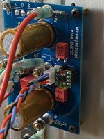
A pre-final-wiring pic to go with the above.
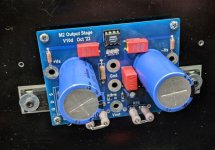
I initially set up with a lab power supply - pulling 1.4A per rail at 28V (per channel). I used 0r6 for the resistors, and I went for this knowing I was going to try running it from a pair of SMPS at 28V. I'm still evaluating how it sounds (local feedback - note Rfb in the pic is removed in the test build) but initial impressions are very positive indeed.
The build was easy enough, and it was easy to set DC offset. It seems stable once everything warms up. Its currently mounted on modushop 5u/300mm heatsinks and both heatsinks get plenty warm, but I think you would be fine with 4u rather than 5u.
Attachments

Fran is using one that he already has for another project. 🙂
Which is why it is 28V (too high for the MOSFETs at 1.4A).
Patrick
Which is why it is 28V (too high for the MOSFETs at 1.4A).
Patrick
For those who are already rushing to the Toshiba MOSFETs :
My advice is that you should build and enjoy this first using IRFP240/9240 (even no Harris).
Only if you really like it, and you think it is worth further investment, should you consider the Toshiba's.
3 years ago, there were already 680 HKD a quad (curve tracer matched at 55°C).
You can see the calculation here :
https://www.diyaudio.com/community/...racer-matched-pairs-quads.342720/post-5916533
Nowadays, you cannot even find fake ones on offer from Aliexpress or Ebay.
Or if they are on offer, they are asking for >100HKD a piece.
Even though the MOSFET costs is nothing compared to power supplies and heatsink cases.
This is meant to be a fun project. So start with a low cost solution.

And the cheapest way to reduce distortion drastically is to include the M2OPS inside the feedback loop. 🙂
Patrick
My advice is that you should build and enjoy this first using IRFP240/9240 (even no Harris).
Only if you really like it, and you think it is worth further investment, should you consider the Toshiba's.
3 years ago, there were already 680 HKD a quad (curve tracer matched at 55°C).
You can see the calculation here :
https://www.diyaudio.com/community/...racer-matched-pairs-quads.342720/post-5916533
Nowadays, you cannot even find fake ones on offer from Aliexpress or Ebay.
Or if they are on offer, they are asking for >100HKD a piece.
Even though the MOSFET costs is nothing compared to power supplies and heatsink cases.
This is meant to be a fun project. So start with a low cost solution.
And the cheapest way to reduce distortion drastically is to include the M2OPS inside the feedback loop. 🙂
Patrick
I had a pair of SMPS300re from another project. They are nominal 30V out, and only adjustable down as far as 28V.
I have to say it sounds very good on first testing which is very promising indeed. To add to Patricks post above, I'm using IRFP240/9240.
I have to say it sounds very good on first testing which is very promising indeed. To add to Patricks post above, I'm using IRFP240/9240.

With 3x successful alpha test, I am pretty sure the PCB is OK.
However, they have all used the local feedback version.
So I shall wait till one of them has tested the global feedback version first before publishing the Gerber files.
Patrick
However, they have all used the local feedback version.
So I shall wait till one of them has tested the global feedback version first before publishing the Gerber files.
Patrick
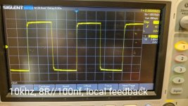
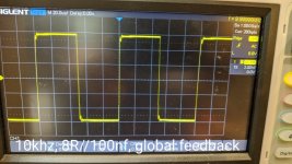
So global feedback also works. 🙂
Both are tested with a reactive load ( 8R // 100n ).
Almost no difference in the amount of ringing (which is expected).
You can always limit the bandwith further if you want no ringing at all with capacitive load.
Patrick
.
Both are tested with a reactive load ( 8R // 100n ).
Almost no difference in the amount of ringing (which is expected).
You can always limit the bandwith further if you want no ringing at all with capacitive load.
Patrick
.
Attachments
Hi Patrick
thanks for sharing this project with us, boards have been ordered and now to start the part sourcing
Do you have a schematic to share with us - there is a draft attached to post #21 which can get us going but want to make sure I use the most recent to ensure for a more accurate BOM to be compiled 🙂
..dB
We have finished our curve tracer matching of 150 pairs 2SK3497/2SJ618 at 55°C heatsink temperature and with Kerafol 86/82 insulators.
Matching criteria is <3mV Vgs at 1.25A, and Yfs to <3%. Meaurement repro is 3mV.
This particular batch (originally from Mouser) has no NNPP Vgs overlap.
So we can only offer NN-PP match, with Vgs difference between NN & PP <0.25V.
This is of no real importance in the M2 OPS, because of DC trimming.
(Your rail voltage difference can easily be of the same order and has the same effect).
From the 300 devices measured, we can only offer 30 quads to the above mentioned specifications.
We shall measure one quad from this batch for distortion first before finalising the values of R13,14.
So patience required.
Patrick
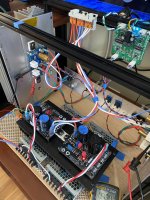
I thought it would be useful to add some comments on listening to the M2OPS. The speakers here are freshly serviced stacked quad 57s, with Miro AD1862 DAC fed by USB or SD card, and 01A preamp. The M2OPS is powered through 2x SMPS300RE switch mode power supplies set at 28V in a Modushop 5u 300mm chassis. This voltage is a little higher than recommended, but this amp was a test bed for others, and hence was used in testing the M2OPS. I'm using BB OP551, and matched Vishay 240/9240. R13/14 are 0r66 (2 x 0r33 in series as that was what I had to hand). I had a bit of experimentation getting cooling right - but once that was sorted out the mosfets sit at 30degC over ambient, and the heatsinks about 25degC above ambient. My advice here is to use good thermal interface products implemented properly. There is SMD involved, but its big SMD 😉.
In terms of set up, the M2OPS was easy to get running, very easy to null out offset. I tried setting up the amp with both global and local feedback, with the scope shots shown earlier in the thread. However, I prefer local feedback. The sound is very beguiling, dynamic, with very good placement and soundstage. Its not as big a soundstage as some other amps I have listened to, but its not something that I was conscious of when listening - only through comparison did I hear this. It is easy to spend a few hours listening with this amp - I don't get any sense of fatigue with it. I tried also to get a handle on why I preferred local to global feedback - and the best wording I can come up with is that with global feedback, the sound was more "damped" or constrained compared to local feedback. There is just a tad more dynamics and liveliness with local FB. I guess that in another setup with different speakers this might be different. Great sense of bass and highs - although bear in mind there are limits with Quad 57s!
In time I will get to bring this to other peoples homes and have a listen with other speakers and equipment and ears. In short I'm impressed - and you might ask, well how does it compare to X, Y or Z amp? Well, your personal preference will play a massive part in that opinion, but I can only answer that by saying that I think it can hold its head up high in the company of the J, F5, other Alephs and more. Given the low parts count with great availability, easy build, and pretty standard power supply, published gerbers and build guide there is not much barrier to trying it for yourself.
Use Kerafol 86/82 :
https://linearaudio.net/sites/linearaudio.net/files/v3 euvl.pdf
I don't use anything else since 2010, other than high voltage (>200V).
For best soundstage, you need to use separate power supplies for each channel.
And as Fran said, this is so easy and low cost to build.
You will have it done in one weekend when you have all the parts.
Patrick
Thanks for sharing your thoughts and M2OPS setup Fran 😉.
This past week was Tweak-a-Night for my M2OPS.
First up, a total psu swap, linear supply was replaced with a pair of MeanWell SMPS units each having a capMx at output. Regulated output voltage was adjusted to +/-23.5VDC in anticipation of the following tweak.
Next, OPA551 was replaced with OPA604 soldered on a DIP8 adapter.
Week Finale, Installed an SE-->Bal converter board (BTSB) to feed a differential signal to M2OPS.
Each step improved my listening experience. The most notable improvement is the drop in background noise, this setup is so quiet LED's and the warm heatsinks are the only way to tell the amp is on. Ear right in front of individual drivers, Total silence from the speaker!
What started out as an easy experimenting amp board has turned into something that will need a proper chassis, Nice project Patrick.
Attachments
I do not understand why you need any external circuit when the design already covers both SE and differential inputs.
An additional SE to BAL converter only brings additional distortion.
This is because the opamp will convert your "balanced input" back to single ended.
Patrick
An additional SE to BAL converter only brings additional distortion.
This is because the opamp will convert your "balanced input" back to single ended.
Patrick
Last edited:
- Home
- Amplifiers
- Pass Labs
- The M2 Output Stage in Class A/B, and maybe a Power WHAMMY?