It will reduce the clipping voltage, and you will want to trim R5 to get TP at half the rails. Generally performance decreases with lower voltage, but it probably won't be too bad.
I am trying to use digital potentiometer DS1882 for volume and tone controls and it accepts power upto +/-7V.. and it needs to followed up with a buffer. So thinking if we can use this buffer with this?
or can we have digital pot running with +/-7V and buffer running with +/-10V or will it complicate the power supply?
I am thinking for a config as below:Run the digipot with zeners off of your buffer supply.
<buffer><tone control with buffer><volume control with buffer>
where volume control will DS1882 and tone control will be active baxandall tone control with potentiometers replaced by DS1882.
here, will using higher voltages for buffers cause any problem with lower voltage DS2882 digital pots, would there be any clipping?
That depends on the output signal voltage of your first buffer. You need to figure out max signal input voltage into first buffer times gain of first buffer. Is the resulting signal voltage something the digipot can manage? Maybe you will need to check out other digipots. There are some that allow higher signal voltage. Yes there is a max to the ds1882 and its not okay to exceed that max signal voltage.
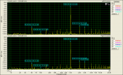
testing Kuarlotron in stereo configuration
here is the stereo version +/-10V
here is the stereo version +/-10V
Attachments

Last edited:
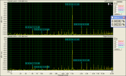
testing with +/-7v5
Here is the stereo version when +/-7v5 POWER SUPPLY
Here is the stereo version when +/-7v5 POWER SUPPLY
Attachments
Last edited:
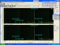
One (left)channel trim for lower distortion
Attachments
Last edited:
That depends on the output signal voltage of your first buffer. You need to figure out max signal input voltage into first buffer times gain of first buffer. Is the resulting signal voltage something the digipot can manage? Maybe you will need to check out other digipots. There are some that allow higher signal voltage. Yes there is a max to the ds1882 and its not okay to exceed that max signal voltage.
This buffer never adds gain.
I could have sworn I saw it configured to add 6dB a month or so ago. Sorry for adding confusion if that's not the case.
I could have sworn I saw it configured to add 6dB a month or so ago. Sorry for adding confusion if that's not the case.
By nature it can't add gain. I've asked Keantoken about it, because it would wide it's application. You'd have a different buffer, if it did.
Yes. Ive been reading through the thread backwards and I dont see it. It would certainly widen the use like you said.
I can't believe how many times I've been asked about that, but even if you add more transistors and complexity, the benefits in the buffer configuration don't carry over.
Here is the stereo version when +/-7v5 POWER SUPPLY
Hi Thimios,
The graphs with different power supply voltages +/-10, +/-7v looking similar. So we can expect similar quality with either of the supply voltages?
I believe so but keantoken is the boss here!🙂.Hi Thimios,
The graphs with different power supply voltages +/-10, +/-7v looking similar. So we can expect similar quality with either of the supply voltages?
I believe so but keantoken is the boss here!🙂.
The design corrects variance from the source. Unless your voltage from the source exceeds the operating voltage you have, you should be ok. However some may state transistors sound better at different voltages, if I remember right.
Voltage changes only change characteristics of parts in the buffer, and in general what's used in this aren't too particular. It's actually got a benefit that a regulated PSU isn't necessarily an improvement unless it has an improved noise rejection or lower impedance.
It all started to make sense, after I understood that it essentially matches signal to signal and that has to include voltage. However as a buffer it'll sink enough current to drive whatever is down the line, to maintain the signal, as is seen on the in. The whole point is that it won't let variance occur, so of course it doesn't add gain or change from voltage input. It's doing more than just providing a lowered impedance, such is typical of buffers.
A random idea:
The way I see it, the Kuartlotron is a fancified version of half a diamond buffer (Q1, Q2) that applies current feedback via the current mirror. What if one were to turn it into a fancified version of a whole diamond buffer by adding a complementary version of the circuit? Would that work? I guess the result would be called an Oktlotron.
Obviously this would double complexity, which may or may not be worth it given that the basic Kuartlotron performs quite well as-is. It should theoretically lower even-order distortion though.
A few simulations later...
Simulated distortion, 5 Vp @ 10 kHz into 10k||2n with BC550C/560C (Cordell, other models in brackets), 1.16 mA + 10 mA, +/- 12 V supplies:
* "half diamond" (pnp + npn EF), resistor-loaded: 0.013% (0.015%)
* Kuartlotron: 0.0014% (0.0027%), CCS-loaded output: 0.0010% (0.003%)
* "half diamond", 2x ideal-CCS-loaded: 0.0008% (0.002%)
Clearly the Kuartlotron gets pretty close to ideal while only using 4 transistors, rather than the 6 you would otherwise expect. Note, however, that it limits maximum signal amplitude to little more than half of what the CCS-loaded half diamond will manage.
All that being said, a full diamond buffer with two 1.16 mA CCS' and optimized output transistor emitter resistors (~13 mV drop each) yields a probably-unrealistic 0.000068% (or more realistic 0.0011%) given the same level and load - this while running the output transistors at ~2.3 mA, so total current draw is down by about a factor of 3. If you are willing to up the transistor count to 8, this seems like the way to go.
I did ultimately get the "Oktlotron" idea to work by inserting an output coupling capacitor to combine the two halves. It does basically work, and 0.0008% (0.0023%) doesn't sound too bad, especially since some trimming could bring this down even further. Way too many adjustments for my taste though.
I think you'd need 8 transistors to a "full" version of the Kuartlotron. But I'm not certain the diamond and Kuartlotron are as related as you think. There's a fair bit of thought into the Kuartlotron. It's offering a design perspective very unlike diamonds.
It seems like you're missing one of the key points is that the Kuartlotron feeds the two primary transistors with transistors, which is in concept much like the Kmultiplier.
It seems like you're missing one of the key points is that the Kuartlotron feeds the two primary transistors with transistors, which is in concept much like the Kmultiplier.
- Home
- Source & Line
- Analog Line Level
- The Kuartlotron - keantoken's simple error-correction superbuffer