OK2700k=2.7M
LTSpice does funny things if you use the M suffix
It's fine in Multisim 😀
With Joachim and Marina's approval of the early design coupled with the improvements you have in mind - it does appear that you have a very viable design. Congratulations.
I may well try a PtP build as a switching + volume control. In the meanwhile I would like to see the initial PS design provided you feel like sharing.
Good luck.
A friend has repeatedly told me this buffer is extremely tolerant of bad power sonically, so I don't know how much of a power supply is needed. I'm satisfied with a passive zener supply at most, but admittedly I have not played with the power supply much.
Can we have a show of hands on which type of supply you guys want? The original version was made for DC for Joachim, but I've had a few requests for a single-rail supply version. I want to stick with dual-rail because that makes capacitors optional, but I understand a single-rail option would be convenient for many.
Last edited:
Power Supply
Why not try it with your Kmultiplier rail filter, preceeded with possibly a Regulator, as i suggested in your Kmultiplier thread last year.
Also i'm guessing that most applications would prefer a Dual Supply ?
I just simmed it with + - 17V & it looks fine.
Why not try it with your Kmultiplier rail filter, preceeded with possibly a Regulator, as i suggested in your Kmultiplier thread last year.
Also i'm guessing that most applications would prefer a Dual Supply ?
I just simmed it with + - 17V & it looks fine.
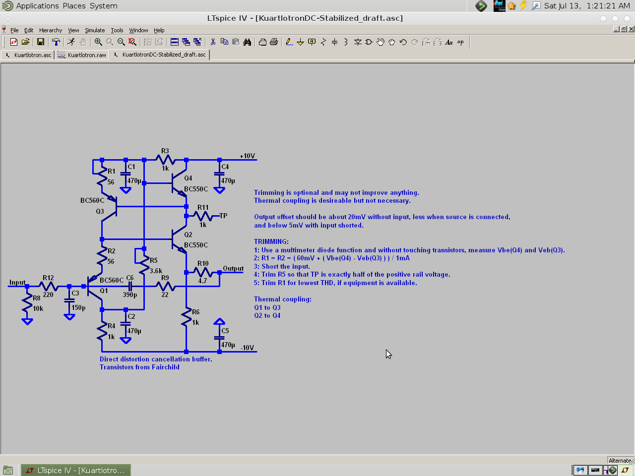
The simulator won't show the thermal mismatch which is what the biasing arrangement is for. That's why I put the TP node at half the positive supply. If you change the supply voltage you probably want to either remove the bias circuit or adapt it to the new supply voltage (ideal solution).
Other reasons for +-10V:
1: It keeps dissipation and therefore dynamic and static thermal drift to a minimum.
2: I found going over 10V had a harsh sound that I couldn't track down, and wasn't even necessary. Perhaps after all the improvements since then it will be fine? I don't know.
The Kuartlotron doesn't draw enough current for the Kmultipliers. You would need 470R resistors from power to ground to draw about 20mA to put the KM's in a good range.
If I wanted just the extra PSRR of the Kmultipliers, I would just use BC3x7-40 C-multipliers, potentially with zeners for regulation, and possibly choose the ground references strategically depending on the ground topology of the system.
Last edited:
An approximate inductor.
I have a 3 step plan for that:
Get an AA battery from the flashlight.
Wind 15 turns of 20ga wire around it.
Put the battery back in the flashlight. 😀
You will have an *approximately* 0.002mH inductor.
Disclaimer: My math skills are awful, so this might need checked--can someone check it with an inductance meter?
P.S.
20ga is thermostat wire from the hardware store.
A 28" piece of 2 conductor may provide enough for stereo.
Tip: Tape the wire to the battery and then rotate the battery.
20ga is a nice solid copper material also great for small signal needs.
You can approximately measure wire gauge with a closed wire stripper tool.
Any recommendations on what to use for the coils L1 2uH ?
I have a 3 step plan for that:
Get an AA battery from the flashlight.
Wind 15 turns of 20ga wire around it.
Put the battery back in the flashlight. 😀
You will have an *approximately* 0.002mH inductor.
Disclaimer: My math skills are awful, so this might need checked--can someone check it with an inductance meter?
P.S.
20ga is thermostat wire from the hardware store.
A 28" piece of 2 conductor may provide enough for stereo.
Tip: Tape the wire to the battery and then rotate the battery.
20ga is a nice solid copper material also great for small signal needs.
You can approximately measure wire gauge with a closed wire stripper tool.
Last edited:
 Hallo Joachim, hallo Keantoken
just give you a picture of my working place and a "certain " 😀😀
buffer in it
The sound has a level of undisturbed, clear information, that is only mached by the very best line stages I came accross in my "Audio Life"
the "musical correctness" in tonality, dynamics, punch, details, focus and imaging is just striking! - in my system the height matters and now, with the newer version its there and also 3D is there ( soundsources/instruments are placed before, behind, above and in between my speakers)
and when this happens a lot of things went into the right direction...
( I use a ZDL 5 way, time correct, and " almost" phase linear speaker as my main monitor and played this weekend with the Kiso speakers - which created a lot of fun - actually real "Joy")
Thanks for your work ....
and my "Amplifier" thanks you too, as it loves being provided with signals from such a wonderful source
Martina
Last edited:
Easycheesy plan for power:
Those nice "MC" regulators from OnSemi are available in 9v positive and 9v negative.
A standard silicon diode, such as 1n5* in series to the center pin will boost it to 9.65v, which is well within tolerances. So, there's an uncomplicated and doable plan for power. 🙂
Those nice "MC" regulators from OnSemi are available in 9v positive and 9v negative.
A standard silicon diode, such as 1n5* in series to the center pin will boost it to 9.65v, which is well within tolerances. So, there's an uncomplicated and doable plan for power. 🙂
Martina, the pictures are a bit small. Can you generate a PNG ?
Martina, you can try my floating idea.
Just cut the ground wires from the batteries that go to the copper ground plane.
REDUCE THE VOLUME BEFORE YOU DO THAT:
Martina, you can try my floating idea.
Just cut the ground wires from the batteries that go to the copper ground plane.
REDUCE THE VOLUME BEFORE YOU DO THAT:
Hi Joachim
... I am off driving to Vienna now, but will take the Kiso and Amp with me
so either there or when I am back I will try that
- signal source then in Vienna might be the Immedia from Michi , his CD Digital pre
or my blutooth Iphone files ;-)
Looooooong drive now!
Good Night!
Martina
... I am off driving to Vienna now, but will take the Kiso and Amp with me
so either there or when I am back I will try that
- signal source then in Vienna might be the Immedia from Michi , his CD Digital pre
or my blutooth Iphone files ;-)
Looooooong drive now!
Good Night!
Martina
OK.
The other could try in simulation if a floating supply works.
I found it works most of the time also with other circuits.
There is much more to say about this but that has to wait for later.
The other could try in simulation if a floating supply works.
I found it works most of the time also with other circuits.
There is much more to say about this but that has to wait for later.
PS
.... I would never "cut" crokodiles nor their clamps...
even though removing crokodiles from ones buffer might need "expertise'
.... Crokodile dundees everywhere
.... I would never "cut" crokodiles nor their clamps...
even though removing crokodiles from ones buffer might need "expertise'
.... Crokodile dundees everywhere

It could work on a floating suppy. So 20V with no ground connection.
A small bit of data:OK.
The other could try in simulation if a floating supply works.
I found it works most of the time also with other circuits.
There is much more to say about this but that has to wait for later.
Yes, that works.
The 50/50 resistor divider used on mine is 400 ohms and 400 ohms (with 0v at centerpoint), and the power is 20v with LM317. Generally, a chip buffer will perform horribly with that setup; however, it didn't bother Kuartlotron at all. It didn't go dull! I could have assembled a chip based solution faster, but it would not have completed quickly due to performance. However, the Kuartlotron assembled reasonably quick, and "scored a home run" with its good performance meaning it was completed. SO, despite messing with transistors and layout, the Kuartlotron, being a plug and play performer, is actually the easiest buffer solution that I know of.
You won't get stuck with resolution and tone issues--those are problems it does Not have.
Any recommendations on what to use for the coils L1 2uH ?
For historical references only, here is the older version of Kuartlotron that doesn't use the inductor. http://www.diyaudio.com/forums/atta...d1373696842-mpp-kuartlotron-dc-stabilized.png
P.S.
I have a model that is older than that and it still outperforms a chip. 😀
P.P.S.
Post #26 has an easy way to build the inductor for the new model.
- Home
- Source & Line
- Analog Line Level
- The Kuartlotron - keantoken's simple error-correction superbuffer