Well I’m finally getting stuck into this project again. I’m posting a progress report to give me some incentive to get moving a bit faster.
The +/-45V power supply board for the front-end is completed, tested and working. The input stage / VAS board is 80% loaded. This circuit is pretty straightforward and there really isn’t any question over whether it will work or not.
The power output stage is a gamble though. Ten pairs of these high fT (as high as ~90MHz peak) TO-220’s in parallel will have a rather high net gm. The thing may work like a dream or parasiticaly oscillate its head off.
Anyway, if that turns out to be the case I’ll just have to ditch the board and resort to a conventional output stage with some pairs of 3281/1302. The board is drilled and lacquered, should get it loaded tomorrow and mounted to the heatsink if I’m lucky. I’ve also made a few revisions to the OPS circuit posted a page back. For better temperature compensation I added a pair of diode-connected TO-126’s in series with the dual transistor VBE multiplier, which mount directly on top of the pre-driver transistors.
Cheers,
Glen
Attachments
I like your SOA calc but is it just for 21193's??
BTW , all the krill SH$&t is here,,
http://71.203.210.93/pdf1/Electronics/Projects/Audio_amp/Frugalamp/OTHER/
OS
BTW , all the krill SH$&t is here,,
http://71.203.210.93/pdf1/Electronics/Projects/Audio_amp/Frugalamp/OTHER/
OS
Only the 1sec 25 degC (green line) SOA is included in the program. I had plans to add pull-down menu with a large selection of SOA curves for popular power transistors have haven't gotten around to it yet.......
EDIT:
Holy c$%p, I can't believe that was 8 years ago already!
EDIT:
Holy c$%p, I can't believe that was 8 years ago already!
"
Bonsai, do not attempt to get around the language censor.
"
confused: 😕
I didn't - that's why it got automatically censored
Thanks Glen - great little routine
Bonsai, do not attempt to get around the language censor.
"
confused: 😕
I didn't - that's why it got automatically censored
Thanks Glen - great little routine
G.Kleinschmidt said:Problem with balanced bridge is that when you split the "single ended" output stage into two, you then have the load current handled by two pairs of half as many devices. That means double the current swing in each transistor
Cheers,
Glen
Supersym... gimic or sonic savior?
Glen,
Nelson Pass uses his supersym topo in PASS high-end amps. Nelson's designs have a large number of output devices. No big deal to Nelson. Does removing the ground reference improve the sound or imaging to Nelson's ears? Glen, have you built and listened to any supersym amps?
Some speakers drop below 1 ohm, could the supersym topo perform better for very low impedance loads?
Thats got to be one of the most over engineered amps I have ever seen.
I come from a background of electronic design and spent most of my life reducing designs down to save money. This design goes completely against that.
I come from a background of electronic design and spent most of my life reducing designs down to save money. This design goes completely against that.
Thats got to be one of the most over engineered amps I have ever seen.
But at least you would not have to spend 10K $ if you DIY it.
We all could just build blameless's or P3A's (not a bad amp),
but as diyer's (our time , less money)we can go beyond
conventional. I once criticized GK's amp designs as being a little ESOTERIC , but some need the challenge of a more
sophisticated design. A good source for stealing better techniques ..too.
Some would make the rails so high and chop the gain so
the amp would never clip (mjl) or do the research to tame
saturation (personal taste)...same end result. 🙂
OS
ostripper said:
Some would make the rails so high and chop the gain so
the amp would never clip (mjl) or do the research to tame
saturation (personal taste)...same end result. 🙂
OS
Clipping is a problem with low power rails but transients get clipped way beyond the normal signal clipping.
I tested a 200WRMS amp with +/-45 volt rails and it it clipped the transients way before I got any decent volume out of it.
On my next build I increased the power supply to +/-60 volts to get a better headroom.
nigelwright7557 said:
Clipping is a problem with low power rails but transients get clipped way beyond the normal signal clipping.
Speaker impedance and sensitivity has sumthin to do with it to, ya know?
I'll be using this amp to drive a 4 ohm speaker 89dB SPL/2.83V.
In my living room transient clipping won't be a problem.
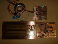
megajocke said:Nice looking boards with all that shiny copper!
Yes, after drilling I rub down with fine steel wool and then spray on the electrolube solder-through conformable coating 🙂
I couldn't bring my self to pay the $90 asking price for 600 grams of tin plate powder.
Cheers,
Glen
G.Kleinschmidt said:
Speaker impedance and sensitivity has sumthin to do with it to, ya know?
I'll be using this amp to drive a 4 ohm speaker 89dB SPL/2.83V.
In my living room transient clipping won't be a problem.
The lower the speaker impedance the less it would affect my amp.
I was testing my amp with an 8 ohm speaker and the transients did clip badly even at fairly low listening levels.
It works!
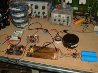
Well so far, anyway. I did not get time to get the power output board fully loaded today, but I did get the whole thing up and running minus the driver and output transistors.
I soldered in two series resistors for the resistor between the emitters of the pre-driver transistors of the triple emitter follower output stage and took the negative feedback from the centre junction.
Attachments
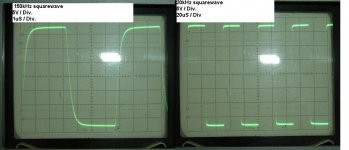
And here is the clipping performance, 2kHz and 20kHz.
The amplifier is currently frequency compensated for a unity loop gain frequency (-3dB bandwidth) of exactly 1MHz using Miller feedback compensation.
This form of compensation returns a high slew rate from the VAS, but comes at a small cost of slight rail sticking on recovering from cliping, as a consequence of the compenation which has to be applied to the Miller loop.
The sticking can be seen in the picture attached. It is only very short, invisible on the 2kHz waveform but obvious on the 20kHz waveform
I explained the cause of this sticking in post 2500 of the Negative Feedback thread here:
http://www.diyaudio.com/forums/showthread.php?postid=1693357#post1693357
Attachments
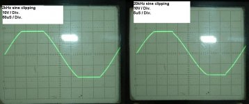
As stated in my previous post, the unity loop gain frequency is currently set to 1MHz, but this will be subject to some tweaking.
I'm rather enthusiastic at the moment over how high I will be able to go with the TO-220’s for power output devices.
Attached below is a close up of the input/VAS board, showing how I mount the compensation components for easy tweaking. I butcher a machined pin IC socket for its individual pins and solder the into the PCB holes for the compensation components (which are then just plugged in with trimmed leads)
When I’ve found the optimal values I just solder the leads of the components into the pins.
Cheers,
Glen
Attachments

LineSource said:Glen, have you built and listened to any supersym amps?
Some speakers drop below 1 ohm, could the supersym topo perform better for very low impedance loads?
Hi
No, I have no experience with the supersym amps. For low impedance loads I do not see any significant advantage for a "bridged" output stage if that is what you mean.
Cheers,
Glen
Well that was in interesting experiment. 
I've now given up on the triple EF output stage using lots of parallel pairs of MJE15028/MJE15029.
The output stage was perfectly happy with five pairs in parallel, but any more than that and parasitic oscillation due to the high gm combined with the high ft is too difficult to keep under control whilst maintaining a satisfactory degree of HF performance.
R-RC / RC snubbers at the bases were effective but killed the HF performance too much for my liking.
There may be come promise for such an OPS with more experimentaion and tweaking, but I do not have all the time in the world so I'll have to shelve this experiment for now.
Three pairs of MJL1302A / MJL3281A will perform better and this is what I'm now redesigning the output stage module / PCB for.
I also have a unity gain current feedback circuit under development to mate with this OPS, which will be built and tested after I get the new OPS operational.
Due to the huge interest in this thread and the projects progress I might even post further progress reports
Cheers,
Glen
G.Kleinschmidt said:Due to the huge interest in this thread
Jeez, just as i clicked/back-buttoned this thread a dozen times again to make the view figure look more attractive.
You think large parallel high fT device output stages are possible only with extreme compact board layouts or SMT's ?
( example )
jacco vermeulen said:You think large parallel high fT device output stages are possible only with extreme compact board layouts or SMT's ?
( example )
Most likely. The output stage I made could be tamed, but at a cost of overall performance inferior to using big TO-264's. What is that thing anyway, an over-kill headphone amplifier? Those SOT-223 without any serious PCB copper are not going to dissipate a great deal of power.
Cheers,
Glen
- Status
- Not open for further replies.
- Home
- Amplifiers
- Solid State
- The Kleinschmidt 25A