What kind of interest would there be out there for a very simple, but good performing 10W class A (into 8 ohms) rated power amplifier:
a) specifically designed to be build as a monoblock.
b) TO-3 complementary BJT output.
c) Of the single polarity supply / capacitively coupled load topology with the esoteric twist of having a common as muck 12AX7 twin triode in the front end.
d) Specifically designed to be built from non-esoteric, cheap, universally available parts.
e) All components (bar the two transformers and one bridge rectifier) PCB mounted for ultra-easy assembly.
I have design I made quite a while ago and considering the popularity of the JHL class A, I’m seriously considering publishing it and having a batch of boards manufactured (to be sold for profit in fame only)
Specifications are not subject to negotiation, and no audiophool blowhard arguments about the evils of coupling capacitors and mixing SS with toobs, thanks.
Cheers,
Glen
The interest is always there if you accomplish something that works. TO3  Why? It's not very wise to use an almost obsolete package. TO220, 218, 247 or similar will just fine.
If you do a pcb you may have room for both TO92 and SOT23, SOT223 parts. Those parts aren't so hard to solder and you will have a lot more types to choose from. You can also make room for 1206 decoupling caps. It costs nothing to do this.
Why? It's not very wise to use an almost obsolete package. TO220, 218, 247 or similar will just fine.If you do a pcb you may have room for both TO92 and SOT23, SOT223 parts. Those parts aren't so hard to solder and you will have a lot more types to choose from. You can also make room for 1206 decoupling caps. It costs nothing to do this.
peranders said:The interest is always there if you accomplish something that works. TO3
If you do a pcb you may have room for both TO92 and SOT23, SOT223 parts. Those parts aren't so hard to solder and you will have a lot more types to choose from. You can also make room for 1206 decoupling caps. It costs nothing to do this.
Hmmmmm....... the TO-3 package will still be with us for some time to come and some of the cheapest and most robust trannies for this application come in T0-3.
If some newbie builds this class A thingie and cranks the bias up too high the first time round, or does a test run on inadequate heatsinks, a pair of TO-3's could be a blessing (especially over TO-220's).
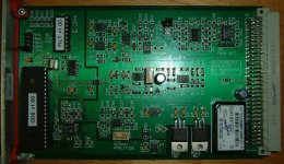
The instrumentation stuff I design / build on a professional basis uses SMD universally (example below), but I don’t think I’ll bother redoing this design for optional SMD parts (sandwiched between big electros, a twin triode and some 5W resistors)......
Cheers,
Glen
Attachments

I think you are doing things much easier using modern parts. You were talking about 10 W class A not 100 W so I can't see the advantage with TO3, only more difficult to mount. In this design job you have also to specify required heatsinkG.Kleinschmidt said:
Hmmmmm....... the TO-3 package will still be with us for some time to come and some of the cheapest and most robust trannies for this application come in T0-3.
If some newbie builds this class A thingie and cranks the bias up too high the first time round, or does a test run on inadequate heatsinks, a pair of TO-3's could be a blessing (especially over TO-220's).
 It's an obvious advantage to keep everything on a single pcb, much less room for error.
If you put a lot of work into this, why not add these small practical things?For me it's not trouble at all to connect a SOT23/223 transistor in parallel with a TO92. It takes me a sconds, maybe a minute.G.Kleinschmidt said:The instrumentation stuff I design / build on a professional basis uses SMD universally (example below), but I don’t think I’ll bother redoing this design for optional SMD parts (sandwiched between big electros, a twin triode and some 5W resistors)......
peranders said:
I think you are doing things much easier using modern parts. You were talking about 10 W class A not 100 W so I can't see the advantage with TO3, only more difficult to mount. In this design job you have also to specify required heatsink
If you put a lot of work into this, why not add these small practical things?For me it's not trouble at all to connect a SOT23/223 transistor in parallel with a TO92. It takes me a sconds, maybe a minute.
It would likely only take me a minute or two to shave my thighs also, but that isn't much of an argument for doing it.
10W class A still gives ~30W idle dissipation. The bias can also be cranked up for 20W into 4 ohms - then we have closer to 55W idle bias.
And sure I can specify the correct heatsink, but that doesn't increase the designs dummy proofness.
Anyway, the board layout was done a while ago already, so it's a moot point.
Cheers,
Glen
G.Kleinschmidt said:OK, here is my little baby. Maybe it will arouse some excitement

My, so many active devices for 10W...
My L'Audiophile Nemesis has only 1 (one) and gives me 12W 😉
Jan Didden
janneman said:
My, so many active devices for 10W...
My L'Audiophile Nemesis has only 1 (one) and gives me 12W 😉
Jan Didden
Well this thread has certainly been worth it so far...........................................
Nice 🙂G.Kleinschmidt said:OK, here is my little baby. Maybe it will arouse some excitement
I have recently gathered loads of "leftover" components from large 24V PSU units at the processindustri I work at. Plenty of heatzinks, large electrolyth's and TO3's (but mostly 2n3055 NPN devices) Maybe a quasi design?
I'm also weak for tubes in amplifiers. I have recently thought on some JLH clone and your project seems to be a similar easy project.
I definately don't like the transformers on the same PCB as the amp though.
If I build something like this hybrid it should definately have this levelemeters implemented 😀
Peak Reading Level Meter Using Indicator Tubes
Radioman62 said:I definately don't like the transformers on the same PCB as the amp though.
That's OK, the transformers aren't on the PCB 🙂
My prototype used 2N3055/MJ2955. Just about everyone has a 2N3055 or two in their junk box, but an MJ2955 won't break the bank though.
Cheers,
Glen
PS
Like the magic eye tube level indicator. I've got some EM84's, but they're reserved as radio restoration spares.
Mr. Kleinschmidt, what did you have in mind here. Release a design or offer pcb's even a group buy?
peranders said:Mr. Kleinschmidt, what did you have in mind here. Release a design or offer pcb's even a group buy?
Both.
I’d like a few professionally made boards for myself, so I figure I could get a batch made up and sell the ones surplus to my needs. Once they’re gone, I would put the PCB design into the public domain and leave any possible further groupbuys to anyone who would like to organise them.
Cheers
Glen
I have EM84's to use for both projects and sparesG.Kleinschmidt said:
PS
Like the magic eye tube level indicator. I've got some EM84's, but they're reserved as radio restoration spares.

I like to do my own PCB's. We have all equipment at my department at work. Even if it mostly would be singleside designs i do. I use Eagle. If I do any artwork i will let it free immediatly I can confirm the amp is working OK. You will need a license for the Eaglecad to work though (a small card for nonlicenced users is not enough for this amplifier). I can also do a GIF picture to write out on film, and of you go with your own PCB work.G.Kleinschmidt said:
I’d like a few professionally made boards for myself, so I figure I could get a batch made up and sell the ones surplus to my needs. Once they’re gone, I would put the PCB design into the public domain and leave any possible further groupbuys to anyone who would like to organise them.
Cheers
Glen
Hope you don't mind if there would be two versions on the same schematic Glen?
Have you done any simulation? What B+ for 12ax7? I like the design. 😎
G.Kleinschmidt said:my little baby.
Count me in, blah blah blah.
(please seriously consider calling it the 10" Kleinschmidt)
janneman said:
My, so many active devices for 10W...
My L'Audiophile Nemesis has only 1 (one) and gives me 12W 😉
Jan Didden
G.Kleinschmidt said:
My prototype used 2N3055/MJ2955. Just about everyone has a 2N3055 or two in their junk box, but an MJ2955 won't break the bank though...
I would be interested in a "big, clunky class-A" design using stock parts, especially if a PCB was available.
It does seem over-complicated compared to some designs eg JLH.
2 transformers and a tube probably do not help.
peranders said:
For me it's not trouble at all to connect a SOT23/223 transistor in parallel with a TO92. It takes me a sconds, maybe a minute.
No SMT please ! not with my eyesight !!
Many people would be put off even if a pcb was available.
G.Kleinschmidt said:
The instrumentation stuff I design / build on a professional basis uses SMD universally (example below),
I wonder if I've used some of your gear ?
G.Kleinschmidt said:
It would likely only take me a minute or two to shave my thighs .....
If you ever get round to it, start a new thread and post the piccies !!! Could be this year's charity event. Donations to DIY Audio.
Andy
jacco vermeulen said:
(please seriously consider calling it the 10" Kleinschmidt)
Maybe even 12" 😀
Hi Glen
Do you have any specs for this circuit, such as PSRR, input/ouput impedance, THD, damping factor, slew rate, etc.
thanks
Do you have any specs for this circuit, such as PSRR, input/ouput impedance, THD, damping factor, slew rate, etc.
thanks
Radioman62 said:I like to do my own PCB's. We have all equipment at my department at work. Even if it mostly would be singleside designs i do. I use Eagle. If I do any artwork i will let it free immediatly I can confirm the amp is working OK. You will need a license for the Eaglecad to work though (a small card for nonlicenced users is not enough for this amplifier). I can also do a GIF picture to write out on film, and of you go with your own PCB work.
Hope you don't mind if there would be two versions on the same schematic Glen?
Have you done any simulation? What B+ for 12ax7? I like the design. 😎
KLe said:Hi Glen
Do you have any specs for this circuit, such as PSRR, input/ouput impedance, THD, damping factor, slew rate, etc.
thanks
OK, here's the deal. I'll have a small batch of boards made up. The prototype was a rats nest perfboard thingie, so before the design gets released in all its glory (component values / PCB layout revealed), I'll build up the working units that I want for myself on the new boards and thoroughly test it first.
I’ll then put the whole design up on the net on a dedicated web page.
The schematic will be revealed for anyone who wants to roll their own, but I won’t release the gerber / Protel files for the PCB until I’ve sold off the surplus ones.
Plate voltage for the 12AX7 is ~100V. Both transformers have a 24V secondary. Transformers with 24V secondaries or dual 12V secondaries than can be series connected are readily available.
I used a little off the shelf 150mA unit for the top (on the schematic) transformer and a cheap 2.5A (60VA) unit for the other.
I have also decided on a minor alteration to the PCB. As well as the transformers and the power rail bridge rectifier, I have decided to redesign for the main 10,000uF filter capacitor to be mounted off board also. Most potential builders would have a collection of salvaged caps, some chassis mount, snap in, etc, so this will save having to specifically order a unit to fit the PCB.
Performance specs are pretty much in line with the Silicon Chip and D.Self class-A designs.
Cheers,
Glen
- Status
- Not open for further replies.
- Home
- Amplifiers
- Solid State
- The Kleinschmidt 10A