poynton said:If you ever get round to it, start a new thread and post the piccies !!! Could be this year's charity event. Donations to DIY Audio.
LOL....... hmmmmmm......
No.
G.Kleinschmidt said:
LOL....... hmmmmmm......
No.
Drat....
So it's not you in the avatar, then ?
Still interested in the amp, though.
Um no, that is Rachel Weisz, the chick that acted in those lousy Mummy movies. And I doubt that she has particularly hairy thighs.
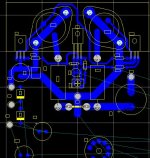
Anyway, with the big filter cap removed from the PCB, the layout of the K10A just didn't look right, so I decided to redo it.
This is as far as I have got, for now. Now I going go away to eat dinner.
Anyway, with the big filter cap removed from the PCB, the layout of the K10A just didn't look right, so I decided to redo it.
This is as far as I have got, for now. Now I going go away to eat dinner.
Attachments
jacco vermeulen said:Wake up, mate, have you seen her eyebrows ?
Newsflash
Oh dear. She probably thinks she's fat too.
MikeW said:I'll take two boards.
Cool 🙂
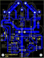
The completed layout is shown below. I'll that I still need to do is tidy up the component overlay.
It will be at least a couple of weeks now before I get the boards from the manufacturer.
Attachments
G.Kleinschmidt said:fat too.
Beep
Maybe her mom is available again.
Leaving the heater coil connections as is ?
Hmm, as a newbie, and not owning a Class A amp yet. I think this would be an interesting build. Especially because I think I could build most out of my junk box. I have a couple of Mullard 12ax7 laying about that need a home.
They look like they would run my Jordan Jx92s well. I'll be waiting for your outcome of testing and pricing of boards.
Chris
They look like they would run my Jordan Jx92s well. I'll be waiting for your outcome of testing and pricing of boards.
Chris
jacco vermeulen said:Leaving the heater coil connections as is ?
Yes, I decided to remove the 120-150 ohm series resistor from the board, as it takes up too much space (dissipates about 3W).
There are three options for powering the heater:
DC, via an externally mounted 120-150 ohm ~10W wirewound resistor from the filter capacitor + terminal.
DC, from an external regulator 12V / 12.6V regulator, for those that want to do it fancy.
AC, from a 12.6V 150mA transformer secondary.
The first one is my recommendation.
I like the fourth option 🙂G.Kleinschmidt said:
There are three options for powering the heater:
To use a LM317 as a current generator giving 0.15A. You also save the tubes from the large inrush current at startup, when they are cold.
By the way Glen, have you seen the Mugenamp design by wimdehaan?
Not to far away from your idees allthough it's not a Class A design.
G.Kleinschmidt said:What kind of interest would there be out there for a very simple, but good performing 10W class A (into 8 ohms) rated power amplifier:
a) specifically designed to be build as a monoblock.
b) TO-3 complementary BJT output.
c) Of the single polarity supply / capacitively coupled load topology with the esoteric twist of having a common as muck 12AX7 twin triode in the front end.
d) Specifically designed to be built from non-esoteric, cheap, universally available parts.
e) All components (bar the two transformers and one bridge rectifier) PCB mounted for ultra-easy assembly.
I have design I made quite a while ago and considering the popularity of the JHL class A, I’m seriously considering publishing it and having a batch of boards manufactured (to be sold for profit in fame only)
Specifications are not subject to negotiation, and no audiophool blowhard arguments about the evils of coupling capacitors and mixing SS with toobs, thanks.
Cheers,
Glen
Glen,
Looking at the VAS transistors, what is the function of the middle
P channel device which has it's E tied directly to + rail and C going
back to VAS IP?
It obviously is a form of local NFB but is there anything beyond that?
Terry
Terry,
Protection - senses current on the VAS degen resistor - some say audible. But you knew this anyway......
Hugh
Protection - senses current on the VAS degen resistor - some say audible. But you knew this anyway......
Hugh
G.Kleinschmidt said:
Yes, I decided to remove the 120-150 ohm series resistor from the board, as it takes up too much space (dissipates about 3W).
There are three options for powering the heater:
DC, via an externally mounted 120-150 ohm ~10W wirewound resistor from the filter capacitor + terminal.
DC, from an external regulator 12V / 12.6V regulator, for those that want to do it fancy.
AC, from a 12.6V 150mA transformer secondary.
The first one is my recommendation.
What about a simple pass regulator, with the pass element mounted on the main heatsink? Would be cheap, simple, elegant. (Of course a single dropping resistor is the most simple/elegant/cheap method. But I really don't like hot resistors.)
AKSA said:Terry,
Protection - senses current on the VAS degen resistor - some say audible. But you knew this anyway......
Hugh
Not sure why he would have asked if he knew what it was for, but I've been waiting for you to appear with some nonsense comments about what "some say" is "audible".
VAS current protection is mandatory, as the VAS, referenced to the +100V plate supply for the 12AX7 is capable of driving the beyond the low voltage rail.
The protection transistor is set to clamp the overloaded VAS current at three time the VAS standing current, which is already guite reasonable at 10mA (so there is plenty of operating headroom).
This VAS current limit works in conjunction with the anti-saturation clamp for the NPN driver transistor, providing a rather good clipping and clip[ping recovery characheristic.
The fact that the VAS current limit doesn't begin to operate until the amplifier is driven well into clipping means that it's impact will be neither measurable under normal operating conditions, nor audible.
Andy L. Francis said:
What about a simple pass regulator, with the pass element mounted on the main heatsink? Would be cheap, simple, elegant. (Of course a single dropping resistor is the most simple/elegant/cheap method. But I really don't like hot resistors.)
I decided against it because it would make the board bigger.
By leaving the heater supply off the board, the builder can choose to use which ever method suits them best.
Kleinschwantz,
I'm glad you felt the need to explain your often verbose designs. This one is not too bad, however, the use of the tube in place of the usual SS LTP has been done before (in Italy, in fact) and would not sound much different to the real thing since its wrapped in a global nfb loop.
I did not comment personally on your use of the VAS protection scheme, if you read closely. You have some sensitivity here, it seems. The design is competent, but unoriginal.
Glen,
Interesting quote from wikipedia regarding weasel words:
I wouldn't waste much time on Hugh's comments.
Interesting quote from wikipedia regarding weasel words:
Weasels mostly speak in the passive voice -- "some say," "it is thought," "critics say" and are most often examples of "stealth-POV." Weasels are an enemy of accuracy and understanding. So many of the pages tagged as POV are replete with them. However, one of the more over used weasel words I've seen is "controversy." Stealth-POV, a subject that deserves a discussion of its own. Please leave the weasels out of articles!
I wouldn't waste much time on Hugh's comments.
Radioman62 said:
I like the fourth option 🙂
To use a LM317 as a current generator giving 0.15A. You also save the tubes from the large inrush current at startup, when they are cold.
By the way Glen, have you seen the Mugenamp design by wimdehaan?
Not to far away from your idees allthough it's not a Class A design.
:embarrassed: Yes, I should have though of that fourth option, which would work well also.
The simple series resistor (cheapskate option) also limits in-rush current, to a degree, as the voltage developed across the heater rises from a low (cold) starting value as the valve warms up.
I have seen the Mugen amp, but to be honest, besides the 12ax7, there is that much similarity to the K10A.
Cheers,
Glen
- Status
- Not open for further replies.
- Home
- Amplifiers
- Solid State
- The Kleinschmidt 10A