MJL21193 said:No, there's more to it. I want these for the "sides" with a bottom plate and a top plate that is 3/16" aluminum and will join with these. This will increase dissipation.
As you have already done the hard part (design, layout and board), I will concentrate all of my efforts into the chassis.
I'm going for a different look here...not retro anymore. 😉
OK, cool (lame pun). I look forward to seeing the finished product.
So, has anyone got one of these singing yet?
Cheers,
Glen
jacco vermeulen said:Oh, look see who's got a bench brake that handles 5mm alloy.
Pretty spacey, nice cornering.
Thanks Jacco,
I can't take credit for the bends - it came that way. A scrap angle - 36" x 11" x 8". No charge. 🙂
gain said:where did you all source the heat spreader the two TO-3's are mounted to? thanks.
I cut mine from a 2" x 1.5" angle. More scrap.
I think they sell aluminum angle stock at Home Depot or others.
Glen,
I have a problem. I have tons of transformers - 24VAC ones by the score, but I do not have a single secondary 30VAC. Push come to shove, I could series a 6V transformer with a 24V.
What is the tolerance on the high voltage supply? What I want to know, in a nutshell, is will a 24V work in place of the 30V? 100V instead of 115V?
MJL21193 said:Glen,
I have a problem. I have tons of transformers - 24VAC ones by the score, but I do not have a single secondary 30VAC. Push come to shove, I could series a 6V transformer with a 24V.
What is the tolerance on the high voltage supply? What I want to know, in a nutshell, is will a 24V work in place of the 30V? 100V instead of 115V?
30V is better but 24V will still work.
Cheers,
Glen
Status report
Hello Glen
You want some progress reports. Here it comes.
My cards have been very near finish since the second day I got them but not completely. I will tomorrow get MPSA92's and also one missing BD140.
I have found my transformers, one that I can get 28.5 Volt under load for the High voltage and one 24 volt, also for both channels. It's just 100VA but it fits so nice together with the rest of the stuff in the box I have dedicated through som sawing, milling and custom make up to fit everything nice with the custom made heatzinks, band sawed to fit nicely 🙂 .
Do you think the transformer is to weak? I have two fatty Philips 15000uF 63V on each side that will help me with the dynamics. You know I will not play and listen to sinus tones at full effekt on this amp. 😀
I could force some things up on a bench to look at the scope on a sinewave tomorrow but I am a patient man and rather build everything up in the box so that after firing up, I am also able to do listening test without to have everything connected like a mess. Also, you have allready confirmed the amp is working OK so far.
Pictures and tests will come later on this cute amp, i promise 😱
I have also considered to order a thick anodized gold front with slots for two EM84 eyes that tells you when the amp is near clipping. Also with the engraving The Kleinschmidt 10A at the front. Do you have any wish for the typeface?
Not an eye will be dry after watching such an amplifier front. Particulary the author would grow in pride. 😉
Hi,
Glen,
Finally got the PCB's, possibly a little while ago as the envelope was hidden under a stack of commercial.
PCB's looking fine , It's going to be a joy to populate them.
Now it's time to collect time......
Glen,
Finally got the PCB's, possibly a little while ago as the envelope was hidden under a stack of commercial.
PCB's looking fine
, It's going to be a joy to populate them.Now it's time to collect time......
A heater tip
About the heater voltage.
I have decided to use the simplest currentlimiting device available. A resistor.
Because I will use only one 24 vac transformer I don't see why I should burn away over 3 watt over that resistors on each channel.
My tip for the day is to connect the heaters for the two channels in serial. I then only need to burn away slightly over 1 watt for both channels. I have to do a cut surgery in one of the cards though
The above explained:
One channel and one PSU = about 33 volt DC. One tube with both heaters in serie is 12.6 V You need to burn away 33-12.6 = 20.4V * 0.15A = 3.06W. You need a resistor 20.4/0.15 = 136 ohm. As Glen suggest in the schematic, between 120 and 150 ohm.
My tip of the day = 33 - 25.2V (the two tubes with all four heaters in serie) = 7,8V * 0.15A = 1.17W (for both channels. I save nearly 5W power to the endstage). You need a resistor 7.8/0.15 = 52 ohm. Do you know something more? I have such a beautiful effect resistor in my scrap box at 51 ohm 😎 I also have a spare one
Re: A heater tip
Your 100VA transfomer is just right. I like the idea with the EM84's 😎 I have no preference WRT the engraving - use whatever you want 😉
Cheers,
Glen
Radioman62 said:Hello Glen
You want some progress reports. Here it comes.
My cards have been very near finish since the second day I got them but not completely. I will tomorrow get MPSA92's and also one missing BD140.
I have found my transformers, one that I can get 28.5 Volt under load for the High voltage and one 24 volt, also for both channels. It's just 100VA but it fits so nice together with the rest of the stuff in the box I have dedicated through som sawing, milling and custom make up to fit everything nice with the custom made heatzinks, band sawed to fit nicely 🙂 .
Do you think the transformer is to weak? I have two fatty Philips 15000uF 63V on each side that will help me with the dynamics. You know I will not play and listen to sinus tones at full effekt on this amp. 😀
I could force some things up on a bench to look at the scope on a sinewave tomorrow but I am a patient man and rather build everything up in the box so that after firing up, I am also able to do listening test without to have everything connected like a mess. Also, you have allready confirmed the amp is working OK so far.
Pictures and tests will come later on this cute amp, i promise 😱
I have also considered to order a thick anodized gold front with slots for two EM84 eyes that tells you when the amp is near clipping. Also with the engraving The Kleinschmidt 10A at the front. Do you have any wish for the typeface?
Not an eye will be dry after watching such an amplifier front. Particulary the author would grow in pride. 😉
Your 100VA transfomer is just right. I like the idea with the EM84's 😎 I have no preference WRT the engraving - use whatever you want 😉
Cheers,
Glen
Some going on pictures
Hi folks
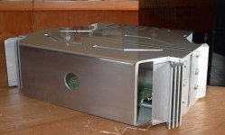
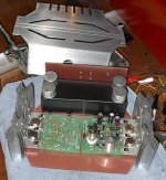
Here is some going on progress pictures. 🙂
Sorry for all other disturbances from my garage. I have just layed the transformers and electrolyths around to get a picture of what it eventually would end up in
I think it looks pretty good so far and maybe I can stress someone more in his building of this cutie 🙂
Besides the black heatzinks, everytning on each shortside (gable ?) is aluminum that serves as heatzinks.


Hmmm ... some Cougar with the 10.5" Centerline rims and 295'rs Goodrich's 🙂 is also there at the right.


Hi folks
Here is some going on progress pictures. 🙂
Sorry for all other disturbances from my garage. I have just layed the transformers and electrolyths around to get a picture of what it eventually would end up in
I think it looks pretty good so far and maybe I can stress someone more in his building of this cutie 🙂
Besides the black heatzinks, everytning on each shortside (gable ?) is aluminum that serves as heatzinks.
Hmmm ... some Cougar with the 10.5" Centerline rims and 295'rs Goodrich's 🙂 is also there at the right.
Re: Some going on pictures
Looking good Radioman. 🙂
My only complaint is that the input RCA is a wee bit close to the speaker terminals. Make sure you wire up the input jacks with screened cable, and don't forget to stuff the inductor and Zobel behind those bananna sockets.
I like the Centerline rims. I wanted to get a set of old school "Autodrag" wheels for my 383cu in machine, but all the American wheels only come with a 4.75" PCD for the hole centers as the closest fit - 0.65mm out for the 120mm PCB of my metric wheel studs.
Cheers,
Glen
Radioman62 said:Hi folks
Here is some going on progress pictures. 🙂
Sorry for all other disturbances from my garage. I have just layed the transformers and electrolyths around to get a picture of what it eventually would end up in
I think it looks pretty good so far and maybe I can stress someone more in his building of this cutie 🙂
Besides the black heatzinks, everytning on each shortside (gable ?) is aluminum that serves as heatzinks.
Hmmm ... some Cougar with the 10.5" Centerline rims and 295'rs Goodrich's 🙂 is also there at the right.
Looking good Radioman. 🙂
My only complaint is that the input RCA is a wee bit close to the speaker terminals. Make sure you wire up the input jacks with screened cable, and don't forget to stuff the inductor and Zobel behind those bananna sockets.
I like the Centerline rims. I wanted to get a set of old school "Autodrag" wheels for my 383cu in machine, but all the American wheels only come with a 4.75" PCD for the hole centers as the closest fit - 0.65mm out for the 120mm PCB of my metric wheel studs.
Cheers,
Glen
Re: Re: Some going on pictures
Yes, I can see what your after ...
It was the extensive milling process that got my brains memory dizzy

I dont think this will be any problem though. I have allready planned for screened cables for the inputs. Also, the bottom and top lids are all plastic.
I didn't quite understand your answer about the wheel rims ...
Why can't you have american wheels on your "383cu in machine"? What kind of stupid machine is it ... any way 😀 For me "383 in" is the size of the engine and have nothing to do with the rims and tires.
Sorry, I may be a noob when it comes to cars from down under 🙂
As a bless I give you a teasing picture ... I could not resist 😀
Centerline Teaser

G.Kleinschmidt said:
Looking good Radioman. 🙂
My only complaint is that the input RCA is a wee bit close to the speaker terminals.
Yes, I can see what your after ...
It was the extensive milling process that got my brains memory dizzy
I dont think this will be any problem though. I have allready planned for screened cables for the inputs. Also, the bottom and top lids are all plastic.
I didn't quite understand your answer about the wheel rims ...
Why can't you have american wheels on your "383cu in machine"? What kind of stupid machine is it ... any way 😀 For me "383 in" is the size of the engine and have nothing to do with the rims and tires.
Sorry, I may be a noob when it comes to cars from down under 🙂
As a bless I give you a teasing picture ... I could not resist 😀
Centerline Teaser
Re: Re: Re: Some going on pictures
Becaussseeee the wheel studs are on a metric diameter of 120mm and the holes in the Yankee wheels are on a 4.75" diameter which equates to 120.65mm.
And no, this has nothing to do with the engine capacity, which is actually a little over 383 cu. in. as the cylinders have been bored 40 thou over. The Australian built engine had a factory capacity of 308 cu. in, but I modified it a wee bit 😉
BTW, why are you are driving around in a puny 351? 😀 Or is this girly car for your wife?
Cheers,
Glen
PS let us know when the amp is working.
Radioman62 said:I didn't quite understand your answer about the wheel rims ...
Why can't you have american wheels on your "383cu in machine"? What kind of stupid machine is it ... any way 😀 For me "383 in" is the size of the engine and have nothing to do with the rims and tires.
Becaussseeee the wheel studs are on a metric diameter of 120mm and the holes in the Yankee wheels are on a 4.75" diameter which equates to 120.65mm.
And no, this has nothing to do with the engine capacity, which is actually a little over 383 cu. in. as the cylinders have been bored 40 thou over. The Australian built engine had a factory capacity of 308 cu. in, but I modified it a wee bit 😉
BTW, why are you are driving around in a puny 351? 😀 Or is this girly car for your wife?
Cheers,
Glen
PS let us know when the amp is working.

I'm waiting on a dual secondary 30V transformer. No rush for my build.
I have one board populated and did a LOT of chassis work. Metallic painted copper on the inside. Black (handmade) steel box is where the 2 24V transformers will go, plus the new 30V.
I expect it will be some time yet...
I have one board populated and did a LOT of chassis work. Metallic painted copper on the inside. Black (handmade) steel box is where the 2 24V transformers will go, plus the new 30V.
I expect it will be some time yet...
Attachments
KLe said:very nice ... beauuuutiful
🙂
Thank you, thank you very much.
G.Kleinschmidt said:Oh c'mon, you at least have to lacquer those nude electrolytics 🙂
I was going to polish them, then lacquer but changed my mind. I have covers for the tubes as well in raw al, but I don't think I'll use these. No sense having the tubes if you can't see them.
Transformer I have on order is a dual secondary 28VAC, 12VA. This was small enough to fit in the black box with the two 50VA 24V transformers. With limited space, I had to locate the caps on top, but this looks ok.
There are now 14 boards left.
May I ask, of the 34 boards sold, are any up and running yet???????
I'm slowly documenting some major updates for my website. I’d appreciate any feedback from those who have made modifications for alternative valves to the 12AX7. It would be nice to document these on my (currently a bit spartan) K10A page.
Cheers,
Glen
- Status
- Not open for further replies.
- Home
- Amplifiers
- Solid State
- The Kleinschmidt 10A