Tell me there was for some time a discussion to put together a GB for custom machined heavy weight platter, like PasslBas is using in his listening room. Was it ever successfull or the idea was dropped?
Seem to remember that there was such a thought about 18months-2 years ago. Also seem to link that with Dave Cawley on this thread. Working on my elderly memory - so please make allowances if I am wrong in this!
Yes I said I would do them, however some were made by another in the USA and the quality was very poor. I'm still open to suggesti0ons.
Regards
Dave
Regards
Dave
The batch that didn't turn out right (pun intended...) were made on a mill from flat stock. The machinists said they had machining accuracy down to one femto - gajillionth of a furlong, which is likely true, however being made from flat stock the process warped the stock and the overall shape was off in a few axis, the errors looking somewhat like a Pringle.
Things that spin really need to be made from bar stock, on a lathe.
Things that spin really need to be made from bar stock, on a lathe.
Anyone has spare SP10 MK2 PCbs laying around?
I was thinking of reverse engineering a limited copies of those PCBs and reproduce them using modern PCB makers.
Mine SP10's pcb has too many jumper link, caused by track lifting using too hot soldering heat ....
Kindly note that this is NOT an attempt to copy, just trying to savage those really bad PCBs in the SP10. I believe many will have encounter the same problem as me...
You can find the pcb drawings in the service manual.
The batch that didn't turn out right (pun intended...) were made on a mill from flat stock. The machinists said they had machining accuracy down to one femto - gajillionth of a furlong, which is likely true, however being made from flat stock the process warped the stock and the overall shape was off in a few axis, the errors looking somewhat like a Pringle.
Things that spin really need to be made from bar stock, on a lathe.
Agreed. Turntable platters work out best when machined via lathe. The cnc mill method can be good, however the cnc programmer/machinist needs to account for the possibilities of material warp and take steps to correct this. It is not impressive that it was not.
-Steve
Depending on prefabrikation method of the metal it could warp after cutting in smaller pieces. Thats why some manufaturer let the platter "rest" for a year, or be placed in a owen for heat treatment, just to get relaxation before the final lathe.
Received my to SP-10 last weeks. One set was ok, the other defective as I was expecting. First I repaired the defective power supply. Two bad caps were causing heavy noise (2V ripple!) on the 32.5V supply line, and one fuse was opened. Replaced both caps and the fuse and the supply was working, except from some little noisier supply compared to my good one. Also the power-on 6V lamp was burned, replaced it with a led. Both supplies are for the rest in perfect condition, with original transistors.
I decided to recap both power supplies. Now both are working just fine.
I decided to recap both power supplies. Now both are working just fine.
Attachments
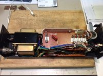
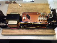
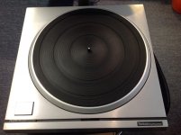
Now the SP-10 itself. All in all both are pretty good physical condition, see example of the good, working one. The perfect one has a burned strobe neon lamp, no problem, I just ordered an original replacement from UK.
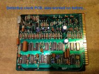
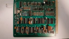
I found the problem of the defective one, if not the solution yet. It is the clock pcb, see picture. It has been repaired, mods previously, and there was damage to the pcb. The first problem is the 3.58Mhz reference oscillator is producing only 1Vp-p instead of the normal 4Vp-p (measured at P1 test point), so the rest of the clock/divider circuit is all stalled, and the two transistors that pulse normally the 140V for the strobe neon lamp are stuck always ON, which apply an heavy load on the 140V supply, that drops at 100V, and their two power resistors overheat, not good...
I tried the good clock pcb from the good turntable into the defective one, and voilà! the turntable was working normally. So it is this board. Good thing to know is that it is not the motor or the drive transistors that are defective. Good...
First I need to have this oscillator up and running. I'll work on the board outside the table using my bench power supply, with only the 5V. I can already see that both oscillator transistors TR201 & TR202 were replaced by unknown type before. That's a start...
Stay tuned😉
Attachments
Last edited:
I decided to recap both power supplies. Now both are working just fine.
I would also change the bridge rectifiers, I have had to do 2 sets on MK3's in the last 6 months !
Dave
Test digital board using only my lab 5V power supply and found that IC2 is defective, very hot and draining the supply. Removed it, installed an IC socket, and ordered the parts on ebay from the US.
Using other transistors from the board (used for switching duties only), I replaced TR218 & TR219 (3.58Mhz osc) with the correct 2SC828A transistors, and clock is now of the correct amplitude at P1 test point. Ordered the correct transistors.
Waiting for the parts to continue...
Using other transistors from the board (used for switching duties only), I replaced TR218 & TR219 (3.58Mhz osc) with the correct 2SC828A transistors, and clock is now of the correct amplitude at P1 test point. Ordered the correct transistors.
Waiting for the parts to continue...
Found this interesting page that list BBC engineers recommended maintenance works: Technics SP-10MKII SP-10Mk2 SP-10Mk3 SP-10Mk4 modifications
They mentioned to replace all motor caps (from Drive Circuit PCB) with Panasonic FC caps. They are C2,4,6 (3x 10uF/50V) and C7,8,12-17 (8x 1uF/50V)
They also mentioned on this page that no cap degradation will prevent the table to work, it will only degrade the performance.
Just to be sure I'll replace these small caps as well in both tables.
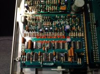
I continue my test of the Digital PCB. First thing I saw after removing the defective IC2 is that the defective PCB 5V current consumption was much higher than the good pcb, 670ma compare to 270ma. I suspect that this table was connected to a defective supply in its past life, and since the 5V regulator is supplied by 12V, a short pass transistor will certainly send higher voltage than 5V to the digital circuit pcb...
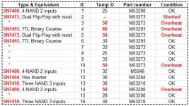
I measured all IC temperature and found some really too hot to be in good condition, or soon to fail. I compare to the good PCB and all PCB are within 28-30C, so anything higher than these value is suspect.
I also realized that these M53 chips are in fact TTL chips, so easy to get by. Here the table of my measurements, and TTL part no equivalent. We can see that IC3, 4, 5 10 and 14 are overheating and need to be replaced.
BTW these PCB are very fragile and I delat with this kind of board in my career. By experience the only way to safely removed the defective IC from the board it to first cut all the IC pin legs with a sharp cutter, then to remove gently each pins from the board using a small tip soldering iron. Then you remove the solder from the pads, and install a good quality IC socket. That insure no damage to the board and easy maintenante afterward.
I'll start installing IC sockets shortly.
Attachments
Well found this incredible site about the SP-10 rebuilding process. Great works:
Technics SP-10 Mk2 Project - mpbarneysources
It is explained how to easily replaced a defective neon strobe using orange leds.
This one also about the recommended maintenance: Technics SP-10MKII SP-10Mk2 SP-10Mk3 SP-10Mk4 modifications
An other great site that has a nice section on the SP-10:
sp10 Gallery
Last edited:
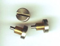
Did you know that the platter screws have a small silicone rubber sleeve over them (see picture), so they fit nicely into the platter holes, I didn't. The bronze color on the screws is not bronze, it is the rubber sleeve...
Found out that I'm missing a few. I measured them to be O.D. 7mm & I.D.5mm. Ordered 1m of silicone rubber tubing from China for a few dollards.
Found out that I'm missing a few. I measured them to be O.D. 7mm & I.D.5mm. Ordered 1m of silicone rubber tubing from China for a few dollards.
Attachments
BBC Rp2/9 Mkii P
I recently got an Ex BBC Rp2/9 P version of the Sp10.
All I got was the motor unit. It was missing the power supply and control unit. Also none of switches were wired up save the speed indication LEDs. Also the switches are missing.
I managed to source an original PSU fairly cheaply as it was defunct. I recapped this and replaced the diodes. Most of the caps were leaking fluid and some were open circuit. That now works fine.
My logic board had no onboard clock source or stop start logic. I've got round this with minimum changes or modifications.
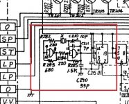
Adding the quartz timing source was simple, all I had to do was fill in the missing components on the logic board and put the redundant half of IC17 into service. See photo I've outlined the area added with a red marker. Also I've marked the circuit diagram up.
This modification is tested and works fine. I can select all three speeds but need to do the VR1 and VR2 cals next as 78rpm is a bit roapy and I can see they are off on my scope.
I recently got an Ex BBC Rp2/9 P version of the Sp10.
All I got was the motor unit. It was missing the power supply and control unit. Also none of switches were wired up save the speed indication LEDs. Also the switches are missing.
I managed to source an original PSU fairly cheaply as it was defunct. I recapped this and replaced the diodes. Most of the caps were leaking fluid and some were open circuit. That now works fine.
My logic board had no onboard clock source or stop start logic. I've got round this with minimum changes or modifications.
Adding the quartz timing source was simple, all I had to do was fill in the missing components on the logic board and put the redundant half of IC17 into service. See photo I've outlined the area added with a red marker. Also I've marked the circuit diagram up.
This modification is tested and works fine. I can select all three speeds but need to do the VR1 and VR2 cals next as 78rpm is a bit roapy and I can see they are off on my scope.
Attachments
- Home
- Source & Line
- Analogue Source
- The Incredible Technics SP-10 Thread