Ah ok,
Yes I will be mounting the motor directly to the plinth and looking at moving electronics into a 2U rack case eventually. So the SP10 chassis will be discarded.
I am also investigating how I can improve the mk2 bearing with a 12mm bearing spindle and larger bearing housing. My thought was to make the spindle 30mm longer this will improve bearing stability and the thicker spindle will improve the interface with the motor rotor. The larger diameter spindle will also increase oil velocity between the spindle and bearing sleeve improving stability. Bearing sleeves will be made from PEEK.
Last edited:
Peek ... what is peek?
There are also different grades of PEEK, I will be using bearing grade for the sleeves, this is impregnated with graphite and PTFE.
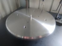
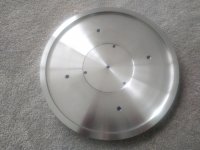
My Stainless Steel platter is roughed out just needs final sizing then I'll post some pics.
Finished the Stainless platter.
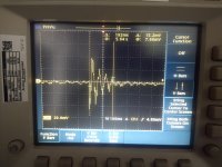
The SS platter is a massive upgrade. I have included a pic of the same impulse response test I did on the stock platter.
Bearing dropped from 300mm Stainless platter with acrylic mat. Impulse decay reduced from 418ms to 192ms.
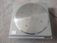
How does it sound - exceptionally good.
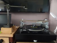
Fitted to my test mule SP10 in the pic.
The SS platter is a massive upgrade. I have included a pic of the same impulse response test I did on the stock platter.
Bearing dropped from 300mm Stainless platter with acrylic mat. Impulse decay reduced from 418ms to 192ms.
How does it sound - exceptionally good.
Fitted to my test mule SP10 in the pic.
Attachments
@warrjon
Lucky you that you have the opportunity to find all the material you need and have the machinery to work it, really!
Lucky you that you have the opportunity to find all the material you need and have the machinery to work it, really!
I've two questions:
1) How does improved impulse decay of dropping a bearing on the platter translate to an improvement during playback?
2) What adjustments have you made to the PLL to compensate for the additional mass? When I experimented with a stainless steel platter many years ago, I found that W&F increased with that much mass.
In response to JP’s questions;
1) Assuming perfectly performing motor and electronics, all turntables are negatively affected to some degree by two noise sources directly coupled to the platter, hence the cartridge: a) the main bearing, b) the stylus reaction forces.
Given that the SP10 mk2 motor and electronics are still near state of the art in performance, addressing the build weaknesses and mechanical compromises give potential for improvement.
I have used the mk2 as my primary turntable since 1998, and I have been aware of the subjective effect of different mat materials and composition. There is a clear ringing to the bare platter, which different mats suppress to varying degrees. The noise sources a), b) will constantly energise the platter resonance, albeit at a low level. However vinyl replay deals with very small signals and the effect of different mats is audible.
I have owned a 10R for two years, and it is obvious that the platter has been much improved. I would call the 10R platter “agnostic”. It doesn’t ring to any degree and it is indifferent to any mat I have tried. Technics themselves have pointed out the effort put into the 10R platter. They claim it improves on the mk3 platter.
Investigating the return of the "flagship" Technics SP-10R
The impulse response of a (linear) system captures the properties of its transfer function and allows prediction of how it responds to any stimulus. In particular the decay time gives information about the time smearing of transients. It is analogous to the information obtained by comparing the impulse response of the various digital filters in DACs.
2) I use the mk2 with TTWeights stainless steel/carbon fibre mat, peripheral clamp and centre weight, total mass 2.7 kg. together with the stock platter mass of 2.9 kg, the total is not that far from Warrjon’s platter. I have not found any audible increase in W&F. I don’t have the measurements but when Warrjon visits in 2 weeks, we should be able to make some measured comparisons. I do recall some original mk2 advertisements that showed a stack of LP’s (50?) on the platter and claims that the performance was unaffected. It was also claimed that the drag of 50 tonearms tracking at 2gm did not affect the measured performance. This was obviously based on their calculations, not actual use. I would anticipate that Warrjon’s high precision machining results in perfect balance and high moment of inertia, far exceeding the stock machined casting. This should benefit the speed stability.
I am sure Warrjon will eventually report the audible results of comparing the stock and new platter.
I do recall some original mk2 advertisements that showed a stack of LP’s (50?)
This......
Yep, that's it. Thanks Pitrus.
I don't read Italian, so I can't tell how many LP's are on the platter, but assuming 50 at 140 gm, the extra mass is 7 kg!
I don't read Italian, so I can't tell how many LP's are on the platter, but assuming 50 at 140 gm, the extra mass is 7 kg!
Yep, that's it. Thanks Pitrus.
I don't read Italian, so I can't tell how many LP's are on the platter,assuming 50
The review does not say how many LPs there were on that turntable, the photo (only that photo) that was posted in the review was taken a few days earlier by the reviewer during the Tokyo Audio Fair in 1976
Last edited:
DIY Stainless Steel platter
1) Using a bearing dropped from a known height provides a repeatable measurement and will make the platter ring at its resonant Frequency. When I did the test I repeated it 6 times on each platter.
There are a few things regarding the impulse and decay.
Platter resonance of the OEM no matter what mat I used was about 40Hz and the Stainless platter about 16Hz. I will verify these again tomorrow.
40Hz is well within the frequency range of the audio signal recorded on the LP. Where as 16Hz is close to the cutoff and there will be little to no information on the LP at this frequency. So any music at 40Hz will excite platter resonance which will then modulate onto the audio signal.
The faster decay of the Stainless platter means it's better damped so far less IMD onto the audio signal, and if there is no 16Hz component there will be no signal to modulate the audio.
2) No PLL adjustments were made. I will be testing W&F and checking PLL tomorrow, along with a host of other measurements.
See Dave Cawley's question and Wayne's response
https://www.diyaudio.com/forums/ana...ble-technics-sp-10-thread-54.html#post4293957
It was Wanye's words that the SS platter was a huge difference that sent me down the path of making my own Stainless Steel platter and I can verify his assessment was accurate. The difference in sound is not subtle and the preliminary measurements I did indicate at least one reason why.
I've two questions:
1) How does improved impulse decay of dropping a bearing on the platter translate to an improvement during playback?
2) What adjustments have you made to the PLL to compensate for the additional mass? When I experimented with a stainless steel platter many years ago, I found that W&F increased with that much mass.
1) Using a bearing dropped from a known height provides a repeatable measurement and will make the platter ring at its resonant Frequency. When I did the test I repeated it 6 times on each platter.
There are a few things regarding the impulse and decay.
Platter resonance of the OEM no matter what mat I used was about 40Hz and the Stainless platter about 16Hz. I will verify these again tomorrow.
40Hz is well within the frequency range of the audio signal recorded on the LP. Where as 16Hz is close to the cutoff and there will be little to no information on the LP at this frequency. So any music at 40Hz will excite platter resonance which will then modulate onto the audio signal.
The faster decay of the Stainless platter means it's better damped so far less IMD onto the audio signal, and if there is no 16Hz component there will be no signal to modulate the audio.
2) No PLL adjustments were made. I will be testing W&F and checking PLL tomorrow, along with a host of other measurements.
See Dave Cawley's question and Wayne's response
https://www.diyaudio.com/forums/ana...ble-technics-sp-10-thread-54.html#post4293957
It was Wanye's words that the SS platter was a huge difference that sent me down the path of making my own Stainless Steel platter and I can verify his assessment was accurate. The difference in sound is not subtle and the preliminary measurements I did indicate at least one reason why.
1) Yes, I've seen this line of thought dozens of times. What I've never seen, and would love to see, is data or evidence of how and to what degree the platter is being excited during playback, and the affect of that on playback.
2) Post that discourse I received an SS platter. My testing showed increased W&F, and I wasn't able to discern a reliable difference in A/B testing. What is your test protocol in determining the difference is not subtle? Do you have needle drops so others can play along?
2) Post that discourse I received an SS platter. My testing showed increased W&F, and I wasn't able to discern a reliable difference in A/B testing. What is your test protocol in determining the difference is not subtle? Do you have needle drops so others can play along?
1) Yes, I've seen this line of thought dozens of times. What I've never seen, and would love to see, is data or evidence of how and to what degree the platter is being excited during playback, and the affect of that on playback.
2) Post that discourse I received an SS platter. My testing showed increased W&F, and I wasn't able to discern a reliable difference in A/B testing. What is your test protocol in determining the difference is not subtle? Do you have needle drops so others can play along?
1) I have thought about this and the only method I can come up with on my setup is to play a 1kHz test tone then modulate that with an external tone and use a spectrum analyser to view the results. My main issue is I only have a soundcard SA and It's minimum sweep is 200Hz and I'm unsure if this is short enough to capture all the artifacts. If you have any suggestions they would be welcome.
2) If I recall there was a QC issue with the later platters Pass Labs had made from flat stock and if the vertical runout was high this would increase W&F. I spent considerable effort to ensure both mounting and top surfaces had minimal runout, I measured TIR in the lathe see video link.
When I measured Bon's platter on my spare motor mounted on the surface plate vertical runout was slightly less than the OEM platter and most of the runout is caused by the motor.
W&F I will be using a software W&F meter, I was planning on DIN and unweighted measurements.
When I said the difference is not subtle I was referring to listening tests, I tend not to bang on about subjective tests because too many use fluffy words to describe what they hear, I'm a qualified Electronics Tech and Metrologist so I like to see the measurements align with what I hear.
The difference in sound between the OEM and SS platter is huge you don't have to sit and listen for subtle differences, it is immediately obvious. What is a needle drop? I would welcome more input.....
Runout test.
Technics SP10mk2 Stainless platter runout - YouTube
Last edited:
Is this the time to ask when we can purchase one of these fine SS platters for our beloved vinyl playback systems? 😀😀
There maybe a possibility I will make more, although I am now investigating having a Gunmetal Bronze platter cast. So stay tuned.
I have spent the morning revisiting the impulse measurements using a more scientific approach as well as other measurements. So without further adieu here we go.
Photos I hope will be in order of the measurements. SS platter is the first photo in each set.
All measurements performed on my main SP10mk2 with acrylic mat and reflex clamp.
Impulse Test averaged over 6 measurements photo just a snapshot of 1 measurement.
The last photo is the test setup used to drop the bearing on the LP so it was repeatable.
SS Platter
Fr = 18.6Hz
Level = 100mV P-P
OEM Platter
Fr = 30Hz
Level = 300mV P-P
Decay was about the same the main difference was impulse level and resonant frequency.
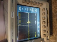
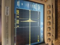
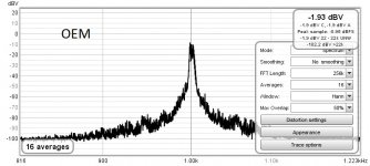
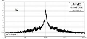
Modulation Test
Modulate a 1kHz test tone with external 40Hz seismic tone This is the biggest indicator to the difference between the 2 platters
18Hz was tired but there was no discernable difference in spectrum plots.
First 2 measurements are 1kHz with no modulation to set the reference which was then used for ALL measurements.
SS Platter
1kHz modulated with 40Hz
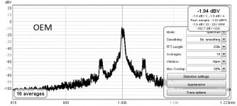
OEM Platter
1kHz modulated with 40Hz
Noise Floor un-modulated groove
No discernible difference between SS and OEM platter
W&F RMS DIN.
SS Platter
0.0732%
OEM Platter
0.0747%
NOTE: The Ulimate Analog Test LP and a software W&F meter was used for W&F measurements. The largest component of W&F was the Test LP being off centre and with a slight warp (Yes this is a new LP). But I was more interested in the comparative rather than the absolute value.
Photos I hope will be in order of the measurements. SS platter is the first photo in each set.
All measurements performed on my main SP10mk2 with acrylic mat and reflex clamp.
Impulse Test averaged over 6 measurements photo just a snapshot of 1 measurement.
The last photo is the test setup used to drop the bearing on the LP so it was repeatable.
SS Platter
Fr = 18.6Hz
Level = 100mV P-P
OEM Platter
Fr = 30Hz
Level = 300mV P-P
Decay was about the same the main difference was impulse level and resonant frequency.
Modulation Test
Modulate a 1kHz test tone with external 40Hz seismic tone This is the biggest indicator to the difference between the 2 platters
18Hz was tired but there was no discernable difference in spectrum plots.
First 2 measurements are 1kHz with no modulation to set the reference which was then used for ALL measurements.
SS Platter
1kHz modulated with 40Hz
OEM Platter
1kHz modulated with 40Hz
Noise Floor un-modulated groove
No discernible difference between SS and OEM platter
W&F RMS DIN.
SS Platter
0.0732%
OEM Platter
0.0747%
NOTE: The Ulimate Analog Test LP and a software W&F meter was used for W&F measurements. The largest component of W&F was the Test LP being off centre and with a slight warp (Yes this is a new LP). But I was more interested in the comparative rather than the absolute value.
Attachments
-
 IMG_20201205_095559883.jpg917.6 KB · Views: 277
 -
 IMG_20201205_095417670.jpg940 KB · Views: 282
 -
 3-1kHz test tone OEM 40hz.jpg87.5 KB · Views: 87
 -
 4-1kHz test tone SS 40hz.jpg87.3 KB · Views: 273
 -
 1-1kHz test tone OEM.jpg87.4 KB · Views: 283
 -
 2-1kHz test tone SS.jpg78.7 KB · Views: 271
 -
 IMG_20201205_100358184.jpg509.3 KB · Views: 122
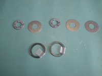
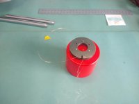
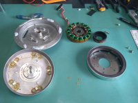
FG Repair
My spare SP10 motor developed an issue, on dismantling it I found one of the FG wires had broken. The only solution was to rewind the FG.
Here are a couple of pics of the FG apart and the rewound coils. The last pic is the motor ready for re-assembly.
Period adjusted and working perfectly. BTW for anyone adjusting the mk2 VR101 and VR102 need to be adjusted then re-checked as VR101 will effect 78RPM and vice-versa.
December 27, 2020 - YouTube
Attachments

- Home
- Source & Line
- Analogue Source
- The Incredible Technics SP-10 Thread