Calvin " Nanook: first two lines of your post..."
sometimes I get ahead of myself. If you are referring to post #152, I am only pointing out that B fields are tougher to base a design around, not that it is impossible. Trying to resolve a relatively complex problem by introducing additional complex solutions can sometimes lead one down a long and prolonged path.
The moving sled (and its contents) will be dominated by the horizontal magnetic "track", so very minute changes to the sled's magnetic field (aligning and creating the arm wand's vertical bearing) can have a profound effect.
As I stated though, the creativity here is good to see, just that one ought to look at the time and effort vs. the outcome. As an exercise, and perhaps as a practical build, it may prove to be more complex than it first appears, and at a substantial cost. if a two point vertical bearing is used with no magnetic alignment on a sled, the problem is only in the horizontal plane, and thus easier to deal with. A Ladegaard using magnetic levitation rather than an air bearing would be analogous.
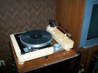
More example of a "folding" tangential tonearm. The Bajulaz tonearm. I really doubt it would work well but I like the fun factor. Here's the description:
"Prototype of the 'Bajulaz' tonearm on a TD-124. It was designed by Ing. Bajulaz to overcome the geometry problems of the conventional tonearms, but allegedly it wasn't so good for the new stereo cartridges and therefore never went in production."
.
"Prototype of the 'Bajulaz' tonearm on a TD-124. It was designed by Ing. Bajulaz to overcome the geometry problems of the conventional tonearms, but allegedly it wasn't so good for the new stereo cartridges and therefore never went in production."
An externally hosted image should be here but it was not working when we last tested it.
.
directdriver...
if the thread was carefully measured, it may be able to be rigged to trigger a lift and and pull the cartridge backwards...
actually all of this stuff pulls me back to the Sakura Sytems (RS Labs) RS-A1 tonearm...
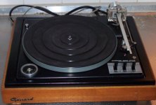
and of course my beloved Garrard Zero 100 SB
bamboo plinth/Sugden added as well
if the thread was carefully measured, it may be able to be rigged to trigger a lift and and pull the cartridge backwards...
actually all of this stuff pulls me back to the Sakura Sytems (RS Labs) RS-A1 tonearm...
and of course my beloved Garrard Zero 100 SB
bamboo plinth/Sugden added as well
Attachments
Last edited:
actually all of this stuff pulls me back to the Sakura Sytems (RS Labs) RS-A1 tonearm and of course my beloved Garrard Zero 100 SB
The Zero 100 has a modern successor in the Thales tonearm and the upcoming new model called "Simplicity". The Simplicity is not 100% tangent but close enough and the Thales Original model is the only pivot arm that's 100% tangent in a pivot design.
An externally hosted image should be here but it was not working when we last tested it.
Since the needle talk" or rid of antiskating by not having overhang of the stylus. I wish more manufacturers can put more research into developing better pivot-linear arms but I guess it's too complicated and expensive to produce. And yet, they rather live with an air pump...."]RS Labs RS-A1[/URL] does not have anything to guide the headshell I wouldn't call it a tangent arm, its purpose is really trying to minimize "needle talk" or rid of antiskating by not having overhang of the stylus.
I wish more manufacturers can put more research into developing better pivot-linear arms but I guess it's too complicated and expensive to produce. And yet, they rather live with an air pump....
.
directdriver...Thales arms...
certainly look to be spiritual successors to the Garrard Zero arms...
The issue I have had with the Garrard arms is their poor pivot bearings, but a single magnet could suffice to keep the "adjusting bearing" ( the one attached to the linkage) from being to sloppy.
AFAIK, the RS Labs headshell has a fair amount of rotation available to it (approx 20°in both directions), and would effectively behave as a tangential tracking arm.
Last edited:
Here's a diagram of the working a Thales arm:
Now, if I eliminate the arm from M to C completely, what is left is the triangle inside the semi-circle that C is always tangent to A. The hitch is that we have to come up with a design to allow the distance between to B to C to change about couple inches. In this case, there's no need for any pivot or bearing at the headshell area at all, just a straight wand. We can have a fixed arm length and the arm's base sit on some linear motion bearing or a tricycle platform that can move front and back and the middle wheel to steer the tricycle in a curved track that allows the arm to be tangent to A at all time. Essentially an assembly that allows pivoting and linear motion at the same time. The vertical movement can be done with a arm with two spikes in the center of the tricycle. Obviously the armwand no longer need to be 12" like the Thales. I think the effective length can be 10" and the moving fixed arm length can be 7" moving along on a 3" track. 7" is chosen as to allow the vertical pivot point at platter level and allows platter that's bigger than 12".
I hope all this makes sense. I will need to have some drawings later.
.
Now, if I eliminate the arm from M to C completely, what is left is the triangle inside the semi-circle that C is always tangent to A. The hitch is that we have to come up with a design to allow the distance between to B to C to change about couple inches. In this case, there's no need for any pivot or bearing at the headshell area at all, just a straight wand. We can have a fixed arm length and the arm's base sit on some linear motion bearing or a tricycle platform that can move front and back and the middle wheel to steer the tricycle in a curved track that allows the arm to be tangent to A at all time. Essentially an assembly that allows pivoting and linear motion at the same time. The vertical movement can be done with a arm with two spikes in the center of the tricycle. Obviously the armwand no longer need to be 12" like the Thales. I think the effective length can be 10" and the moving fixed arm length can be 7" moving along on a 3" track. 7" is chosen as to allow the vertical pivot point at platter level and allows platter that's bigger than 12".
I hope all this makes sense. I will need to have some drawings later.
An externally hosted image should be here but it was not working when we last tested it.
.
I love this forum....
I am a true "vinyl-freak", and a strong believer in analogue tech. "all the way"... through the years I've collected a dozen or so "workable" record player's. And I've been lazy, and is currently using and old "Luxor" LP-player, with a a different tonearm from Ortofon(both arm and pickup).
And with my own RIAA-stage(MC) with 2xEF86 and ECC83(per ch.), and the filter is placed in the NFB loop(e.g. active). It actually sounds quiet nice, and it didn't cost me a "gizillion $$$"....🙂.
But with about 0.2mV@1kHz(5cm/sec.), I chose to use two pentodes - high-µ tubes. EF86, and 'slowly amplified' the 200 - 250µV from the pickup, and I placed the RIAA-correction filter, between the output/input of the ECC83, which I have coupled in SRPP mode. So the signal is "un-touched" by the two pentodes, and each EF86 amplifies the signal about ten times(volt), so I have 0.2V rms when it reach the last stage. and I aimed for exactly .775V rms, for total amplification(from pickup to line voltage, rms). These days 1V rms is commonly used as "line-level", but I'm stuck in the past 😀 (though I was born in the 70's).
Well this reply seems to have nothing to do with the topic on this thread, but I've been so inspired by all yours ideas, that I'm going to build my very own Turntable, with vintage an new parts, old-school and contemporary. I thought about using a MCU for monitor the speed, so I get 33.3 turns/sec. And a neat display, telling me the rpm, output voltage, noise/hum and so on.
But here comes the big question;
Direct or Rem(belt) drive...?
It seems like every body have there own opinion about this!
So if you have an opinion(like a***s, everybody has one...😉), please tell me yours!
Last edited:
Direct-drive, idler-drive, or belt-drive?
They all can sound good and have different flavors. I have tried using two identical direct-drive turntables together, one platter driving the other platter via a belt(tape), an idler, and direct. They all have different flavor. I think the sonic character matches the compliance and material of the interface. In this experiment, the belt drive sound is fluid, delicate, and smooth; the idler-drive sound is robust, warm, and lush; the direct-drive sound is clean, precise, and forceful. They all can sound good and all depends on how they are implemented.
Of course they all need a good tonearm, preferably a well designed linear tracker if someone can come up with a good DIY design. 🙂 Back on track, please share your tonearm designs!
Have fun!!
.
joaquim, way off topic
it may be better to do a search first, then post a new thread if need be. Regarding the parallel tracking arms, even the Thales is off topic, except the results can mimic the linear trackers.
As dd points out, everyone has their preference. There are terrible designs of direct drive,bBelt drive and idler drive. There are also truly excellent examples of each as well.
to me the limiting factor is often some of the poorest arms ever being placed on otherwise respectable decks. Obviously an Ortofon arm (vintage), SME 3009 or similar can be excellent, but there are many plastic POS that hold a lot of decks back.
Last edited:
Just a suggestion
If you want smooth steel tubes with tight tolerances, then look at AIRSOFT barrels (air guns) from japan, but not the stock barrels, the upgrade barrels are exactly 6.01 mm(inner diameter), and the barrels come in different lengths. You can find them at RedwolfAirsoft.com I hope this can help some one and, I have been amazed by how much knowledge this forum contains. Thanks
If you want smooth steel tubes with tight tolerances, then look at AIRSOFT barrels (air guns) from japan, but not the stock barrels, the upgrade barrels are exactly 6.01 mm(inner diameter), and the barrels come in different lengths. You can find them at RedwolfAirsoft.com I hope this can help some one and, I have been amazed by how much knowledge this forum contains. Thanks
Magnetically Levitated Linear Tonearm
Did you ever get to finish this mag-lev linear tonearm project? Please share!
.
Did you ever get to finish this mag-lev linear tonearm project? Please share!
.
Suspect that the Loong & involved 'theorem' linked to may have substance.
Simple experimentations with a collection of Neodym magnets quickly/clearly demonstrates that stabilty is a Problem.
A non starter despite it being an attractive 🙂 idea.
The stoopid /simple Needle point bearing/fulcrum (a single one) is IMO all that's actually required
Simple experimentations with a collection of Neodym magnets quickly/clearly demonstrates that stabilty is a Problem.
A non starter despite it being an attractive 🙂 idea.
The stoopid /simple Needle point bearing/fulcrum (a single one) is IMO all that's actually required
The stoopid /simple Needle point bearing/fulcrum (a single one) is IMO all that's actually required
I think the vertical movement intended to have TWO needle points but the side view made it look like a single one.
As far as stability is concerned the attracting magnets at the bottom helps to tightened the gap to add stability. It's possible but the enormous magnetic field will be hard to shield even with U-metal. Maybe the armwand is long enough for the cartridge to be far away enough from the magnets. Short armwand like the Trans-Fi approach will not work in this design.
I hope Calvin will respond...
Hi,
when I drew the sketch, I didn't knew the E-Theorem.
Since my ressources and budgetsare limited, I concentrate rather on projects with a higher chance for succes 😉
One might think, that the E-Theorem wouldn't apply here if the movement of the carriage slider is restricted to two dimensions only, under which condition static field levitation should be possible.
But I came to the conclusion that a free hovering slider can't be regarded as a 2- dimensional only device and that any so small deviation in the repulsive forces between the left and the right side magnets (in the crosssectional view) should lead to a force in parallel to the sliders long axis.
Maybe that the needle of the pickup would exhibit a larger resistance than the driving force, which could keep the needle in the LP track.
But that would be due to a test.
Still though I'm in the meantime quite convinced that the system as sketched won't work.
If anyone wants to try out, at least one of repulsive magnet pair sides should be changed in direction, so that the fixed mounting body (in grey) functions as back iron or flux guide.
jauu
Calvin
Hi,
Maybe that the needle of the pickup would exhibit a larger resistance than the driving force, which could keep the needle in the LP track.
But that would be due to a test.
Still though I'm in the meantime quite convinced that the system as sketched won't work.
If anyone wants to try out, at least one of repulsive magnet pair sides should be changed in direction, so that the fixed mounting body (in grey) functions as back iron or flux guide.
With permanent magnets magnetic levitation is not possible, only with the help of electromagnets and control electronics.
- Status
- Not open for further replies.
- Home
- Source & Line
- Analogue Source
- The Ikea curtain rail air parallel tracking tonearm!