I would have thought a bobbin with some multicore solder wound on it would be easier use, as you could wind on what you wanted to achieve say 3 gms at the cartridge and then trim it with a thread and nut.
Baggins - this enables you to get a clamped tight counterweight that is relatively dense, thats all. This means you can get it close to the pivot easily... The density of copper and lead are easy to find, and the materials are readily availible - so you can quickly calculate how much length of pipe, lead and end caps you may want (as pipe with two end caps may be enough for a truely flyweight CF arm....)
The VTF can simply be adjusted by sliding the pipe back and forth before fully tightening the fitting.
As I said just an alternative pathway...
Owen
The VTF can simply be adjusted by sliding the pipe back and forth before fully tightening the fitting.
As I said just an alternative pathway...
Owen
I think using two V-groove bearings will work gliding across a rail of knife edge for horizontal movement, and the rocking front to back takes care of the vertical movement.
V-groove bearing source:
http://www.vxb.com/page/bearings/CTGY/V-Groove-Bearings
V-groove bearing source:
http://www.vxb.com/page/bearings/CTGY/V-Groove-Bearings
Hi,
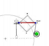
tjust my idea for a lowmass, frictionless and noise-free magnetic horizontal bearing, combined with a 2-blade/2-pin vertical bearing.
jauu
Calvin
tjust my idea for a lowmass, frictionless and noise-free magnetic horizontal bearing, combined with a 2-blade/2-pin vertical bearing.
jauu
Calvin
I'am calling your bluff Calvin on the 2-blade/2-pin vertical bearing and I'm raisin you by a horse shoe. Now show me your cards.
the green magnets are ROhS compliant of course 😉
What's with the blueish ones? 😉
On topic: looks heavy, what masses would you attribute to the respective parts? Additionally, the levitated magnets (carrying the floating base) look too small. Weight and/or couping to the pickup would also have to be considered. And not to get carried away too much, but with the pivot being a needle, what's the gain of the whole magnet thing anyway - wouldn't at least noise and friction be comparable to a fixed base?
Where's your first prototype? 🙂
Cheers,
Sebastian.
.
Calvin,
I like the idea and thanks for sharing the diagram. I especially like the bottom attraction magnet to tighten the gap to add rigidity - after all magnets are a compliant system, the smaller the gap the more precise horizontal movement. Using two needle points as vertical bearings is also an excellent idea. I wonder why people don't do that more often and always stuck with knife edge bearings. Two needle points have the least friction and by adjusting the height of one needle, you get azimuth adjustment!
I do have concern with the mass. Can you place the needle point, vertical pivot, at the bottom of the slider so the over all height is lower and the mass is lower? Since the stiffness of the gap is at its strongest at the bottom of the V tray so place the pivot point there makes sense to me - less wobbling. The pivot point should be at the level close to the record surface, of course as your drawing hints. Also you can place the whole assembly above the record and have the armwand much shorter, like the Souther, if you choose. The bottom of the slider can contain some oil for damping the vertical movement - after all the slider is really a v-shape tray.
Thanks again for showing the diagram. It makes me think of it as a magnetic Ladegaard arm. I think your design is brilliant! I look forward to a prototype.
.
Last edited:
I like your thoughts as well, Calvin.
Here is the air-bearing referred to earlier in the thread, circa 2006.
http://www.newwayairbearings.com/ad...hings_combined_nwab-09-040-v03-2009-02-27.pdf
Scroll down to page 3 of the pdf.
Here is the air-bearing referred to earlier in the thread, circa 2006.
http://www.newwayairbearings.com/ad...hings_combined_nwab-09-040-v03-2009-02-27.pdf
Scroll down to page 3 of the pdf.
a tough row to hoe...
great to see the creativity here, but...
mu metal or not, the total magnetic field of the slider will dominate anything you do with a "levitated" horizontal sled/"track". We are talking very small fields required to to build with, unless a very large mass (relatively) would be required. This moving mass will add to the amount off dampening required, which will add more mass...
Engineered solutions should not be required further engineering to allow use. The idea is to reduce complexity, while providing the desire performance.
Do ultra low friction bearings have a benefit? Of course. I'm just not sure of the increased complexity and high precision machining is worth the cost of doing, when ultra simple and effective bearings can be made or purchased that can help address many of these problems.
As per the drawing a few posts back, you can easily see that the total field will be dominated by the horizontal "track" bearings, and as there are no magnetic monopoles. The fields will be complex, with some sort of field attenuation or moderation in some space and some sort of field increase in others.
This is a worthy project in and of itself, but the required effort could easily out-weigh the benefits and (most likely) increase the likelihood of introducing other problems.
Murray, how've you been? 🙂
Last edited:
Good Stew hope you are also. I knew Calvin wasn't bluffing I just called his hand to see his cards. Its really great to see people having ideas and stimulating discussion.
I am sure Calvin has done some knock ups or he would not have posted. You have to try thing, it will be interesting to see how this pans out. Besides you can never have too many magnets they help keep the food fresh in your refrigerator (I think I saw that on YouTube or was that in a pyramid?)
I am sure Calvin has done some knock ups or he would not have posted. You have to try thing, it will be interesting to see how this pans out. Besides you can never have too many magnets they help keep the food fresh in your refrigerator (I think I saw that on YouTube or was that in a pyramid?)
This is a worthy project in and of itself, but the required effort could easily out-weigh the benefits and (most likely) increase the likelihood of introducing other problems.
I still think it's still simple enough for a DIY project and certainly simpler than an air-bearing design. The idea is there so all it takes is some tweaking as you suggested to "reduce complexity." I definitely see the potential there. If Calvin can reduce the mass, he can reduce the magnetic force along with it, hence less complexity.
I say go for it!!
.
The R&D and tweaking required to get an idea working well can be substantial. There are DIY folks who take the time to do so because they have the need to work on their ideas and there are others who DIY because it's the only way they are going to be able to afford the toys they want. Sometimes its a bit of both.
Every now and then it does not hurt to have a little reality check though. I have seen an air bearing linear arm and while it is not a design I want to pursue it appears to be well made with a good finish and a very attractive price.You can purchase one of these for $599.00 plus a pump. I guess I ask my self could I build this myself and if the answer is yes I ask could I do it to this level of fit and finish for this kind of money? I am including some quantity of time as having a value in this process. So when I see a product like the MG-1 tonearm it makes me give my head a little shake and ask myself If I would really want to build one or just buy one and enjoy it. It is good to see folks work this hard at designing and manufacturing a product like this and for keeping the price so very reasonably low. Kudos to the guys at this company.
Sometimes things like this help me to get hold of where my ideas are going and get back to asking how much it is going to cost. Then I can readdress my goals with the thought in mind to figure a way to make the design realistically affordable. So I thought I would insert this here just as a point of reference.
Advanced Analog Audio - MG-1 Air Bearing Linear Tracking Tonearm
.
I have an idea that I want to share just for yucks. Don't take it too seriously. But it does have its historical precedence in the Marantz SLT-12. What I have in mind is much simpler but it still requires 4 pivot points, 6 ball bearings for horizontal movement. And then 2 needle pivot bearings for vertical movement like Calvin's. Certainly a far cry from your typical uni-pivot arms! Obviously it's a little bit too Rube Goldberg.
Straight trackers certainly can throw us a loop in the head! Fun mental exercise, anyway.
P.S. I just refuse to use or think about air-bearing, it's just not my thing - we already have to deal with so much just to play a damn record and having an air pump in the house is off limit for me. I wouldn't even deal with pumps for fish, why would I want that for record playing. Besides, where's the fun in inventiveness? I will continue to rack my brain on coming up with tangential non-air-bearing designs.
An externally hosted image should be here but it was not working when we last tested it.
.
just for yucks idea...
may not be too way out there. The inclusion of a horizontal "rail" to hold the carrier in the horizontal plane perfectly aligned might help as well. . You could then run a small wheel attached to a bobbin, to draw the arm across the record, being driven by the platter itself.
may not be too way out there. The inclusion of a horizontal "rail" to hold the carrier in the horizontal plane perfectly aligned might help as well. . You could then run a small wheel attached to a bobbin, to draw the arm across the record, being driven by the platter itself.
Attachments
Last edited:
Brilliant! But wouldn't the arm move from left to right when the platter is spinning? You forgot to add a squirrel pedaling the platter as motor drive in order for it to reach the nut on the headshell. :-D
Seriously, it's not only hard to design without air-bearing, it's even harder to design without using linear motion bearing. A purely pivot bearing linear tracker only exist in the Thales tonearm.
.
Seriously, it's not only hard to design without air-bearing, it's even harder to design without using linear motion bearing. A purely pivot bearing linear tracker only exist in the Thales tonearm.
.
Hi,
@sek: blue is the green of Mars, I guess ;-)
@nanook. Sorry, but I´m not able to understand what You want to tell me with the first couple of lines of our post??
One should understand that my sketch was a qualitative one not a quantitative. I´m too short of time for such a project at the moment to execute tests or a prototype myself.
Indeed, as directdriver relized, the basic idea is due to the Laadegard arm, which also separates the tasks of horizontal and vertical movement between two different bearings. The two-needle or two-blade bearing is imho close to perfect to handle the vertical part. Depending on construction it allows to vary the azimuth and the damping and to easily change cartridge/tonearm-wand combinations. As DD pointed out different constructions of the slider may allow for lowered pivot points and other improvements.
So remains left the task of creating a frictionless noisefree horizontal and linear bearing.
Roller bearings -with or without blades- fulfill none of the two demands in detail. Still though they might be well enough to suit the task more than sufficient.
Air bearings fulfill both tasks, but the needed air supply is typically noisy without additional and voluminous noise reduction measurements. The sleeve-and rod type air bearing like in the Kuzma is very stiff, which I consider a great plus (and it elegantly combines both bearing axis in one bearing).
An magnetic bearing could fulfill both tasks without additional large components/devices. It would probabely stiffer than the Laadegard air-layer bearing, but less stiff than the sleeve-rod system (btw. wouldn´t it be great if one could use a magnetic sleeve-rod system? But afaik there are no radially magnetized cylindrical magnets or half-pipes). A magnet bearing could fit small dimensions and be of low moving mass and could be rather easy DIYable. If one for e.g raises the ´opening´ angle from the suggested +-15°to+-20° to +-45° the similarity to the Laadegard becomes very obvious. Basically the air layer would be replaced by the action of the magnetic fields. As a first test one could use the same angled aluminium profiles as the Laadegard uses and glue some magnets on.
I don´t know if the idea is practicable at all...it might e.g prove difficult to source those thin, long linear magnet rods. The magnetic stray fields may also create problems (but then then there are magnet assisted designs like the Schroeder where the magnetic fields obviously don´t do any harm).
jauu
Calvin
Last edited:
Posted a somewhat similar idea here
http://www.diyaudio.com/forums/analogue-source/46976-tangential-arm-floating-magnets.html#post525491
although I sort of envisioned the static magnets clamped between two pieces of of angle bar, just like the Ladegaard. In principle this or Calvins idea should work, but longitudinal stability might be a problem, or ...???
- Status
- Not open for further replies.
- Home
- Source & Line
- Analogue Source
- The Ikea curtain rail air parallel tracking tonearm!