Hello
I would like to know if someone have successful ever built these amplifier ?
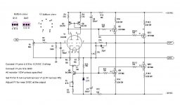
http://digilander.libero.it/essentialaudio/hybrid_circuit.htm
I'd like the simplicity of the amplifier but my friend warn me he built these amp couple years back and at the firs power up it did blew up .
For me a bit somehow unbelievable these circuit can work with vertical mosfet but also lateral mosfet in Class A mode with out any parts need to be exchange.
You can read that on the bottom under the sign PCB & KITS
Also for Class A he calculate the x-former the same voltage like to the Class A/B . He calculate the power supp. voltage after rectification by 1.4DCV . That is unbelievable with these high bias .
If the amp biased in 3A /or 4A/ channel you can't get more than 1.2DCV after rectification under load . That mean if I use 25V transformer will give me under the load around 30VDC not 35VDC . Am I wrong ?
Usually the need different circuit for lateral and vertical power mosfet ? Something fishy with these schematic .
Probably the guy didn't put up the right schematic , because he sell PC boards , kits for the amp ? But in that case He supposed to warn the people the schematic posted is not with the right values !
Please if someone built these amp successful let me know .
Also would you please comment the sound of the amp .
Greets
I would like to know if someone have successful ever built these amplifier ?
http://digilander.libero.it/essentialaudio/hybrid_circuit.htm
I'd like the simplicity of the amplifier but my friend warn me he built these amp couple years back and at the firs power up it did blew up .
For me a bit somehow unbelievable these circuit can work with vertical mosfet but also lateral mosfet in Class A mode with out any parts need to be exchange.
You can read that on the bottom under the sign PCB & KITS
Also for Class A he calculate the x-former the same voltage like to the Class A/B . He calculate the power supp. voltage after rectification by 1.4DCV . That is unbelievable with these high bias .
If the amp biased in 3A /or 4A/ channel you can't get more than 1.2DCV after rectification under load . That mean if I use 25V transformer will give me under the load around 30VDC not 35VDC . Am I wrong ?
Usually the need different circuit for lateral and vertical power mosfet ? Something fishy with these schematic .
Probably the guy didn't put up the right schematic , because he sell PC boards , kits for the amp ? But in that case He supposed to warn the people the schematic posted is not with the right values !
Please if someone built these amp successful let me know .
Also would you please comment the sound of the amp .
Greets
Attachments
I have seen something similar.
🙂 .. of course .. because I have seen so much in all years in audio
In one borebely Headphone amp.
A Hybrid Tube/MOSFET Headphone Amplifier
by
Erno Borbely
Special Article, pdf:
http://www.borbelyaudio.com/special_articles.asp
http://www.borbelyaudio.com/pics/405borbely2506.pdf
Good luck with this one.
Even for loudspeakers, Tubes can make good sound & great amps.
Headphones can really shine in pleasant HeadPhones amplifiers.
yours, Line 'linie' Lineup
gaborbela said:Hello
I would like to know if someone have successful ever built these amplifier ?
http://digilander.libero.it/essentialaudio/hybrid_circuit.htm
This schematic keeps appearing over and over and has been discussed before on this site, at length (search???). The amp as drawn has several problems which may well result in smoke. Even when te errors are corrected, the general idea is not a very good one. For starters triodes are not pentodes, MOSFETs, bipolars - the input stage will always be unbalanced in this topology. Not to mention that the operating voltage for the tubes is too low to get enough current to drive MOSFETs, that the MOSFETs are asked to dissipate way too much, that the output wil clip asymetrically, that the current source is designed so it is not thermally stable, and in fact it's biassing is fitered wrong so it may blow up on startup, taking your speakers with it...
As usual, do not believe everything you find on the internet, even if there is someone selling kits of it.
Hello
Thank you for your reply .
OK I pas these amp .Even I like Hybrid design but probably there is better design out there .
Greets
Thank you for your reply .
OK I pas these amp .Even I like Hybrid design but probably there is better design out there .
Greets
My hybrid amp is described below(sorry in Japanese).
http://ja1cty.servehttp.com/mosfet/mosfet2.html
The current of MOSFET is 1.5A and voltage is +/-16V. Therefore
thermal dissipation of each MOSFET is 24W (16Vx1.5A). I used a forced
air cooled heatsink for a pair of MOSFET(top and bottom ones).
Therefore each heatsink handles 48W(24W+24W). If MOSFET operation
assumed 35V, 3A(105W/each MOSFET). very big heatsink is required.
The outlooking of my amp is seen below.
http://ja1cty.servehttp.com/mosfet/FET-outside.jpg
Re: Re: The Hybrid Class A amplifier
Ilimzn
Think you are very right.I have heard this before .. the last time I did see this Borbely Amp in forum.
So it must be changed to be safe.
gaborbela
you and your freind has some intestesting Hybrid ideas.
The idea is good. I would like to wsee more of Tube + MOS + BJT Class A amplifiers.
Which are properly tested and does not smoke.
If anybody else has some better similar great idea
than I be a Happy Lineup
thanks gaborbela.
Dont give up Hybrids
Your friend from sweden: 'linie' Lineup
ilimzn said:This schematic keeps appearing over and over and has been discussed before on this site, at length (search???). The amp as drawn has several problems which may well result in smoke.
Ilimzn
Think you are very right.I have heard this before .. the last time I did see this Borbely Amp in forum.
So it must be changed to be safe.
gaborbela said:Hello
Thank you for your reply .
OK I pas these amp .Even I like Hybrid design but probably there is better design out there .
Greets
gaborbela
you and your freind has some intestesting Hybrid ideas.
The idea is good. I would like to wsee more of Tube + MOS + BJT Class A amplifiers.
Which are properly tested and does not smoke.
If anybody else has some better similar great idea
than I be a Happy Lineup
thanks gaborbela.
Dont give up Hybrids
Your friend from sweden: 'linie' Lineup
Szia Béla,
I don't recommend this amplifier. There are some problems with it.
1st: R13-C4. This filter takes the hum, and rail noise into the amplifier circuit.
2nd: The mosfets has large input capacitance, and the tubes low current is not able to drive them easily.
Sajti
I don't recommend this amplifier. There are some problems with it.
1st: R13-C4. This filter takes the hum, and rail noise into the amplifier circuit.
2nd: The mosfets has large input capacitance, and the tubes low current is not able to drive them easily.
Sajti
Szia Sajti
In Hungarian
Igen valoban valaki meg epitette ezt az erositot es az elso probara felrobbant .
Szoval nem erdekel egyaltalan .Konyu lett volna megepiteni mert a nyakrajz adott hoza de ha nem mukodik csak vesztegetem az idomet es a penzem vele .
Koszi a tanacsodat
Udv Gabor
In English
Yes one of my friend did built these amp and at the first try it blew up .
Even it would be easy to try it because it has the layout I don't want to wast my money and time with it .
Thanks for the advise
Greets Gabor
Hello ja2dhc
Post #5
My hybrid amp is described below(sorry in Japanese).
http://ja1cty.servehttp.com/mosfet/mosfet2.html
The current of MOSFET is 1.5A and voltage is +/-16V. Therefore
thermal dissipation of each MOSFET is 24W (16Vx1.5A). I used a forced
air cooled heatsink for a pair of MOSFET(top and bottom ones).
Therefore each heatsink handles 48W(24W+24W). If MOSFET operation
assumed 35V, 3A(105W/each MOSFET). very big heatsink is required.
The outlooking of my amp is seen below.
http://ja1cty.servehttp.com/mosfet/FET-outside.jpg
It is a really nice simple well design amplifier . I Google the power mosfet unfortunately hard to find part .At least not in North America .
These is a lateral mosfet or vertical .
It is possible to replace it with 2SK type of Hitachi or Toshiba or may be with IRFP mosfet .
Thanks for the schematic .
Greetings
sajti said:1st: R13-C4. This filter takes the hum, and rail noise into the amplifier circuit.
How do you filter your HT supply ?
ja2dhc said:My hybrid amp is described below(sorry in Japanese).
http://ja1cty.servehttp.com/mosfet/mosfet2.html
The current of MOSFET is 1.5A and voltage is +/-16V. Therefore
thermal dissipation of each MOSFET is 24W (16Vx1.5A). I used a forced
air cooled heatsink for a pair of MOSFET(top and bottom ones).
Therefore each heatsink handles 48W(24W+24W). If MOSFET operation
assumed 35V, 3A(105W/each MOSFET). very big heatsink is required.
The outlooking of my amp is seen below.
http://ja1cty.servehttp.com/mosfet/FET-outside.jpg
It is very nice amp. Night and day difference from that Italian one.
MJL21193 said:Why not try this one: K10A .
I built it and the performance is very good.
Glen K probably has some of the boards left too.
BECAUSE ja2dhc's amp WILL SOUND BETTER than Glenn's. Try and compare.
Push-Pull and Single-Ended, Apples and Pears.
Unless you're into a transmission line and full lone ranger mood.
Those FS22SM's are hefty beauties.
Unless you're into a transmission line and full lone ranger mood.
Those FS22SM's are hefty beauties.
Yep; Also, diffcascade VS asymmetrical amp. Like fresh pears VS apple juice from concentrates artificially flavored. 😉jacco vermeulen said:Push-Pull and Single-Ended, Apples and Pears.
How do you do, Sajti, from Japan. The circuit schematic of my hybrid
amplifier is based on your amp whose schematic is seen below.
http://www.geocities.com/ResearchTriangle/4055/SEMOS.JPG
You used IRF-540 as the MOS FET.
Regarding to MOS FET, I used a small packaged one (I2PAK package)
at first then it became easily burn out due to heat problem. I changed
to TO-3P packaged one (FS22SM-12A) then it did not become heat
problem. I believe whatever kind of MOS FET in TO-3P package with
following electrical spec can work in my schematic.
D-S withstanding voltage : 100V or bigger
Max Current: 10A or bigger
Max Input capacitance: 8000PF or less
One of my fried in Japan successfully made a similar amp with different
MOS FET with TO-3P package and forced air cooling heatsink as shown
below. His amp does not have heat problem, either.
http://ja1cty.servehttp.com/mosfet/nakai-amp.jpg
Wavebourn said:
Like fresh pears VS apple juice from concentrates artificially flavored. 😉
Whatever...🙄
Put both out of sight and play them through the same speaker - you won't "taste" the difference. Pretending that you can is fine though.
Carry on.
🙂
ja2dhc said:How do you do, Sajti, from Japan. The circuit schematic of my hybrid
amplifier is based on your amp whose schematic is seen below.
http://www.geocities.com/ResearchTriangle/4055/SEMOS.JPG
You used IRF-540 as the MOS FET.
Please say him Hello from Wavebourn who lives on an opposite side of the Earth, but shares his approach to audio design!
- Status
- Not open for further replies.
- Home
- Amplifiers
- Tubes / Valves
- The Hybrid Class A amplifier