Here's my contribution to this effort. I finished wiring last night, hopefully I can get to a smoke test tonight. My philosophy is much like George's: no highly exotic parts and minimize the number of suppliers (to reduce shipping costs). So far it will end up between $90 and $100.
An externally hosted image should be here but it was not working when we last tested it.
An externally hosted image should be here but it was not working when we last tested it.
Well, my amp may look cool but it sounds like ^%$&^% squared unless you set it for a clean sound. It does that very good. After spending two nights getting frustrated and resisting the strong temptation to smash it, I remembered my experience with AMP1.0.
I decided that I put far too many parts in the board, so tonight I am channeling up the spirit of Mad Man Muntz again and ripping out anything that isn't absolutely needed. First off my "top secret" mosfet based gain modulation system. I made it do some cool things like compression, expansion, long sustain, and super expressive dynamics in a previous solid state design about 15 years ago, but I had +/- 15 volts and opamps to work with.....So out it comes. So does $3 worth of parts and one control. Some, or all of the mosfet followers are coming out too. They are about 75 cents each and there are 4 of them. Bye,Bye....
Fenris. Do I see an Antek toroid being used as an OPT? I have some on order, should be here Tuesday. I have tried about a dozen different "things" for OPT use. I get 20 watts out of my amp with a real OPT. The "real" AES OPT drops that to 15 watts, and everything else is worse, some far worse. I have a little power transformer that only makes 4 watts with this board and it gets hot due to resistive losses. The same transformer works OK on AMP1.1 since the current is much lower.
Last edited:
Antek transformer for both power and output (50 VA 240v for power, 10 VA 5v for OPT). I've had good success with toroids as OPTs, I've measured them and they're far more linear than some inexpensive ones like Hammond. With the limited power and budget requirements it seemed appropriate. Plus I needed a 5v transformer for the right ratio and there are so few that are appropriate.
That was the extremes of the amp. With the pots instead of switches it is possible to adjust the amount of overdrive (and to some extent the symetry) any where from none to extreme.Grimp,
I checked out your circuit diagram at the time, but missed listening to the audio clips. Just did though. I like the clean, but am not much fan of the crunched sound of your amp.
It is just my personal taste so others my love both! I hardly can hear the hum and only occasionally hear it. So, it is probably not much of an issue.
I have to say that I think your layout is most probably responsible and the cause of your hum issue.
That was pretty much my conclusion, along with the extreme high gain possible with the amp.
Based on the video clip, it would seem that the sections are intermingled rather than are in separate logical sections. You may not have any hum issues at all if you were to separate the sections on your board, like PSU, Power amp, PI, 3rd, 2nd, 1st preamp.
...snip...
I tried to separate them as best I could,and used coax between sections. The breadboard does not lend itself to segmentation unless I rework the Power Supply.
This is the first time I've built this size amp and I'm still learning the nuances of the system.
Thanks for the input.
I think I'll work on amp 1.A and add a feature.
I got a 5T120, a 5T160 and a 5T240 so I could try my amps at several different voltages. I got these last week. I yesterday I ordered a 1T150 a 1T175. These are for bigger amps in the 40 watt range. I got a AN0509 for use as an OPT. I have used toroids as OPT's before. Some don't work, some work OK and some work great. Never tried an Antek though.
Dang! Try to make a clean high gain amp and it will oscillate every time.
Try to make a phase shift oscillator for a tremolo circuit and the blasted thing puts out a dampened oscillation at best, and nothing at worst.
Try to make a phase shift oscillator for a tremolo circuit and the blasted thing puts out a dampened oscillation at best, and nothing at worst.
Dang! Try to make a clean high gain amp and it will oscillate every time.
Try to make a phase shift oscillator for a tremolo circuit and the blasted thing puts out a dampened oscillation at best, and nothing at worst.
Gimp,
I know how you feel, been there and done the same thing!
As far as layout is concerned, there is only one way to learn what works and doesn't, trial and error. If you work on and/or build enough amps, sooner or later you start to have a feel for what works and what gives you nothing but problems. I have seen several amps made by major and I mean very well known and respected companies who built amps with less than satisfactory layouts and sold them for a lot of money to clients. One could argue what is and what is not good layout for an amp, but when there are several ground connections (creating many ground loops) one can no longer say it is a good layout! So, next time you open up the hood of a well known brand amp, just look for the number of areas ground connections are made! In most you will find several! The really good layouts have only ONE ground connection!
As you said, you have not done many amps like this before, it is perfectly normal to have some teasing issues. The main issue is good sound and your amp has good clean sound. It is a good starting point for your new layout as you will end up with less hum and just the crunch sound needs addressing. Keep at it. You are heading in the right direction.
TKS Hunoz,
I tried to keep the main filter caps in a group with the coupling resistors with them. Then used their common ground as the common to all sections (pseudo star ground).
I went back last night and changed to twisted pairs wherever I could for power and ground to each section. This cut the noise in half.
If I have no scope probes attached I get 240mVrms noise on the output (Floating without secondary connected to ground) with the gain set to 1000. If I connect the a probe ground to any ground point in the amp, it decreases significantly (to 28mVrms). So I definitely have a ground problem on the bench.Note that a gain of 1000 will only require 4mVrms in to bring the output to the verge of clipping in a clean setting, so this is excessive gain and I can't see any reason to operated with this much gain.
WRT trem,
Insufficient loop gain does not make for a good oscillator. I was using a triode with Mu=46 whereas most trem circuits use a 12AX7 with mu=100. Just not enough gain to oscillate. I switched to using the pentode as the oscillator and triode as buffer.
Tremolo is now working, but needs tweaking as the waveform is heavily distorted (not a nice sine wave). This results in a pulsating sound rather than a smooth variation. Max frequency does not give a pleasant sound but below 4hz it sounds much better.
I think I can squeeze it in and keep it under budget by changing the current t/p from a 6GH8A ($3) to a 6KE8A ($1) or any other t/p on the dollar menu and adding a second same tube. It becomes a 4 tube amp, but with variable overdrive and tremolo it is pretty neat.
I guess I'll build it on a chassis eventually, although probably not in time for the deadline so the bench unit is it for now.
Last edited:
Last night I did my best Muntz impersonation and I ripped out about 15 parts. I also rewired the amp to move the tone stack to be connected to the master volume pot between the 4th gain stage and the PI. I also increased the grid stoppers from 4.7K to 240K carbon comps, and the gate stoppers on the 2 remaining mosfets to 27K carbon comp. One of the plate load resistors broke in half as I moved it and it was in the stage that was oscillating so I replaced it.
I flipped the switch this morning and was rewarded with good sounds NO oscillation and minimal hum. Running the volume control to max (between the first and second gain stage) and setting the master at just a crack above off results in a super cranked overdriven sound. Turning the master up to loud allows massive feedback driven infinite sustain controllable by where you are standing relative to the little 8 inch speaker. Running the master up full and setting the volume with the other volume control gives a perfectly clean sound. The regions between the 2 extremes are now usable where it wasn't before.
I played with it for about 2 hours this morning trying to get a grip on playing the guitar. I have really lost that ability. My left hand goes numb after about 5 minutes.
After a while I started detecting a bad sound. It sounded like a speaker does as the voice coil starts coming unglued and the wire starts rattling. This is a brand new Jensen Alnico.
Fortunately it wasn't the speaker. It seems that tubes designed for the tuner in an old FM radio don't like being rattled by sitting on top of the speaker. Within about an hour of playing loudly, but nowhere near maximum, one of my tubes had become highly microphonic. So microphonic that turning up the master results in instant howling feedback without a guitar plugged in.
I popped in a new tube and cut loose. It didn't take long before I rattled the grid loose in a second tube. It seems that the "F" note on the first string excites a resonance in these tubes. Playing that note for about 5 minutes can rattle a brand new tube.
I thought I had a rather unique circuit allowing the use of a single isolation transformer to run everything...including the tube heaters. The heaters are all in series and run directly from B+ on DC. This limits the tube choices a bit. I am now searching for a suitable substitute tube that fits my design criteria. Or maybe I can try another brand but these are Mullards.
I really want to hear this amp cranked on the 12 inch speakers, but that means that I have to finish the 12 inch cabinet. On the other hand I want to hear this amps big brother. That means I need to finish the other board.......Decisions.....decisions......decisions.....
Strange you are experiencing microphonic tubes, I just had to replace a 6F4P because it went microphonic. Nasty sounding bugger.
I'm thinking about ordering a spring reverb tank to play with. It will push the cost over the top , so I'll add it when I build the final unit that won't be part of the comp.
Is there any risk of exceeding the Vhc (heater to cathode) of the tubes?
I'm thinking about ordering a spring reverb tank to play with. It will push the cost over the top , so I'll add it when I build the final unit that won't be part of the comp.
Is there any risk of exceeding the Vhc (heater to cathode) of the tubes?
Last edited:
I'm thinking about ordering a spring reverb tank to play with.
I went over to my rental storage warehouse early this morning (you can't go there now its toooooo hot inside) to fetch some tubes. I found some 20EZ7's which are series string 12AX7's, and a bunch of cool compactrons. While digging around I found an old reverb tank. I think I took it out of a dead Kustom PA amp that I stripped for parts a few years ago. I don't know if it works but it looks OK. It will get used in one of my designs, probably with a sand state driver.
Is there any risk of exceeding the Vhc (heater to cathode) of the tubes?
I am running all the tubes in my amp within their ratings, although one output tube is right at the spec limit. The tubes I am using were designed for European series string radios. I designed a rather strange power supply that uses 8 diodes. Is has a bridge off of the 120 volt secondary to run the heaters and output tube screens. It also has two seperate voltage doublers operating out of phase to make a full wave doubler to supply 320 volts for the main B+.
The decision was made in favor of populating the big brother amp. It uses some tasty looking sweep tubes that have a 50 volt heater. I can't find any specs for them so I'll just crank em up!
I designed a rather strange power supply that uses 8 diodes. Is has a bridge off of the 120 volt secondary to run the heaters and output tube screens. It also has two seperate voltage doublers operating out of phase to make a full wave doubler to supply 320 volts for the main B+.
I'm interested in your power supply, too bad I'll have to wait to see the schematic.
Microphonics - The nasty surprise.
I can avoid the problem only if the amp isn't sitting on top of the cabinet. Of course, this is not practical. It can't be a winning design if you can only use it under certain conditions. LOL.
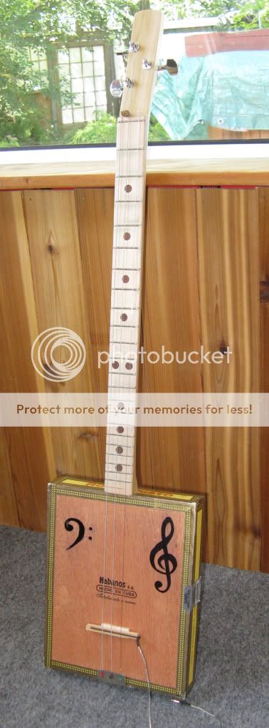
Fenris - I like your amp. The idea for your chassis is original and looks good. I may use it in the future.
Is there any risk of exceeding the Vhc (heater to cathode) of the tubes?
Yes, I believe there is. It will create arcing between the heater and cathode. So, I would not go there.
I'm interested in your power supply, too bad I'll have to wait to see the schematic.
Here is the Eagle schematic that I used to lay out the board. The amp circuit as originally built was highly unstable, tended to oscilate and there was no transition between clean and cranked past 11. The two extremes sounded pretty good though.
I have since ripped it up a bit but I don't plan to make a new schematic until I get it just right. The mosfets in the cathodes are all gone. That stuff didn't work. They act as varaible resistors to control the gain. They can be controlled by a voltage source that goes up, or down with the loudness to control the playing dynamics. It worked great in the solid state world but not here. I will save those tricks for my microprocessor controlled amp in the future. Two of the mosfet followers are gone. I had, and still have too much gain, so I ditched them.
A second board with bigger output tubes is being populated now. I think my next design will put the preamp, power amp, and power supply on different boards. This just makes my life easier since once one part is working I don't need to build it all over again to test some changes in he other part. They will all get put back on one board in the end.
The power supply has not changed and it works good. The heater and screen supply is about 140 volts and the main B+ is 320 volts. The power transformer is a Triad FD8-120 which should be capable of powering a bigger amp, but this guy makes 20 watts as built without tweaking it. Ignore R34 it wasn't used. All the caps in the supply are 47uF 250 Volt except the output cap which is 47uF 450 Volt.
Attachments
Here is the Eagle schematic that I used to lay out the board.
Great. The power supply cleverness will be useful for another project I have in mind. The rest....I get dizzy after seeing so many parts. 😀 Kind of glad it didn't work out sound wise - it fits my philosophy. Muntz is my friend.
I also have decided to build the preamp in a separate box. Less hassle. The phase splitter and power amp is finished and will stay unchanged. Sounds great. The preamp and tone stack will be the key to the final sound of the amp. I'm going to try many ideas and different tubes.
That board was concieved while away from my lab and most of my notes. I kind of threw several ideas on to the schematic then weeded a few out as I tried to fit it all on to the PC board. The layout was finished on a plane flight home. It's easier to rip stuff off of a PC board than it is to add it. Although you wouldn't know it if you saw the board now. There are flying connections two deep in places and I am still tinkering with it.
I have been having numbness and stiffness isues with my hands on and off for two years. I can only play the guitar for a few minutes at a time, so I have been playing with the amp for a while, then soldering on the other board for a while.
I think I am going to get up early tomorrow and go over to the warehouse before it gets too hot and dig for some more tubes and goodies. I went through the two boxes I brought home this morning and didn't find what I was looking for, but found stuff for several more new ideas. Wonder what cool sounds I could get out of a beam deflection tube? What about a quadrature demodulator tube? Can you use one of those useless dual pentodes like the 6BU8 for a PI? More experiments coming.......
I think that supply would be nice if you reversed the filament supply rectifiers to generate a bias supply.
It could solve a vexing problem I've been facing.
I will try it for sure.
It could solve a vexing problem I've been facing.
I will try it for sure.
I think that supply would be nice if you reversed the filament supply rectifiers to generate a bias supply.
Diodes D1 and D2 are also part of the voltage doubler that generates the main B+. Turn them around and the doubler wont work.
The easiest way to make a low voltage bias supply is to hang a zener in series with ground. It will reduce the B+ by the zener voltage though. I had that working on AMP1.0. In fact I used two zeners with ground in between them to generate +/- 6 volts.
AMP2.0 now comes in regular strength, and for a really big headache there is the new Extra Strength Formula. Just set all the knobs on 10 and you will have a really big headache.😀
It sounds pretty much the same as the regular version, but louder. Oddly enough it is about $3 cheaper since the tubes cost less.
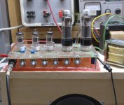
The bubble wrap between the board and the speaker cabinet seems to cure the rattling death to the input tubes, but these tubes are from a different supplier and a different heater voltage. They were just as bad as the Mullards before I put the bubble wrap in. I can now crank away without feedback through the board or rude sounds from the speaker. The gain is high enough to get infinitely sustained notes with the volume and master on 5 and the guitar in front of the speaker.
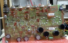
Note all the empty holes in the board. Yes the Mad Man left a lot of parts out, and it still works good!
Next up I will finish the 12 inch speaker cabinet, then build a box for one of these amps. As much as I tend toward maximizing things, I think I like the regular strength one better, but I may change my mind after tinkering some more. The regular sized one makes for a box with the correct proportions. The Extra Strength version will be too tall.
After that I plan to see if I can build a 6 volt heater version of this design, but the tubes are not available for reasonable money. I must search out some good alternatives, hence breaking the design into smaller pieces.
I have a PC board laid out for a 4 tube version of AMP1.0 but I won't make it until I have at least 1 other board to do.
It sounds pretty much the same as the regular version, but louder. Oddly enough it is about $3 cheaper since the tubes cost less.
The bubble wrap between the board and the speaker cabinet seems to cure the rattling death to the input tubes, but these tubes are from a different supplier and a different heater voltage. They were just as bad as the Mullards before I put the bubble wrap in. I can now crank away without feedback through the board or rude sounds from the speaker. The gain is high enough to get infinitely sustained notes with the volume and master on 5 and the guitar in front of the speaker.
Note all the empty holes in the board. Yes the Mad Man left a lot of parts out, and it still works good!
Next up I will finish the 12 inch speaker cabinet, then build a box for one of these amps. As much as I tend toward maximizing things, I think I like the regular strength one better, but I may change my mind after tinkering some more. The regular sized one makes for a box with the correct proportions. The Extra Strength version will be too tall.
After that I plan to see if I can build a 6 volt heater version of this design, but the tubes are not available for reasonable money. I must search out some good alternatives, hence breaking the design into smaller pieces.
I have a PC board laid out for a 4 tube version of AMP1.0 but I won't make it until I have at least 1 other board to do.
Attachments
- Home
- Live Sound
- Instruments and Amps
- The Hundred-Buck Amp Challenge