Replacing the LED with a 5V ref fixes it too, without changes to the PCB. Do you agree?
Jan
It seems that would work, yes. RP3 must be increased in proportion (factor of [new LED voltage]/1.6) to compensate. Some fine tuning of RP3 may be needed to bring the output voltage back to exactly 40 V.
5 V or anything over 3 V is safe.
It seems that would work, yes. RP3 must be increased in proportion (factor of [new LED voltage]/1.6) to compensate. Some fine tuning of RP3 may be needed to bring the output voltage back to exactly 40 V.
5 V or anything over 3 V is safe.
Actually, the beauty of a defined 5V ref is that no R tuning is required - the R ratio is now 35 to 5. The problem is reduced to finding two resistor values that come close to this 😉
For instance, 15k and 2.15 k (E96 series) would give 39.88 V nominal. I would think that is good enough for government work 😉
Jan
If you have an accurate reference. What did you have in mind? Preferably simple, stable, yet quiet ...
I found some measurements I made when I build this pre.
Starting just with the actual subject, the supply line.
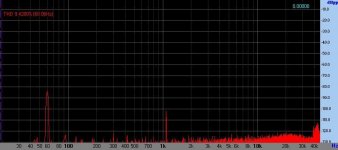
I loaded each output with 10k (simulating some post preamp loading), applied the signal with my invese RIAA to obtain somne 1,4Vrms at each output. So I measured the "intrusion" (or modulation) in the reg output, please see the attachment. I direct apply the PSU line to audio board with a 2200µF capacitor and some zener-R protection, so zero dB is basically the overloading sound board point (almost 2Vrms).
Unfortunately I don't saved the LM317 trial but is worse than this (so in practice this reg is better than trying to use some LM317 in real life).
At earlier posts ago (almost at beginning of this thread) I commented about this.
Starting just with the actual subject, the supply line.
I loaded each output with 10k (simulating some post preamp loading), applied the signal with my invese RIAA to obtain somne 1,4Vrms at each output. So I measured the "intrusion" (or modulation) in the reg output, please see the attachment. I direct apply the PSU line to audio board with a 2200µF capacitor and some zener-R protection, so zero dB is basically the overloading sound board point (almost 2Vrms).
Unfortunately I don't saved the LM317 trial but is worse than this (so in practice this reg is better than trying to use some LM317 in real life).
At earlier posts ago (almost at beginning of this thread) I commented about this.
Attachments
Last edited:
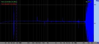
Using the channel-subtracting function in VA analyzer I measured the IN-OUT response, using my reverse-RIAA box. Note the perfect response, at least against my own reverse RIAA (made with well-measured components and checking in VA against deviations from intended response and results accurate).
Pardon about the past 22kHz noise, is my configuration accidentally at 44.1kHz or 48kHz at this time.
Pardon about the past 22kHz noise, is my configuration accidentally at 44.1kHz or 48kHz at this time.
Attachments
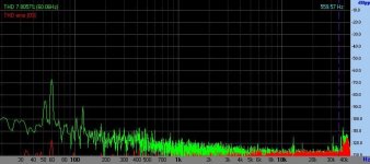
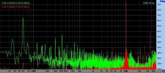
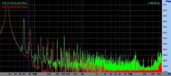
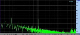
And about input short-circuited noise results from using BCY58 specimens? In GREEN channel, at "more clean" figure attached.
And I made several FFT readings but I found only 2, buried with electrical grid noise (I don't believe I saved with that noise level 😡
 😀 , please read the red traces as card reference and GREEN is the phono out signal). And ~33kHz spike is from screen monitor.
I used 27Hz in bass for discriminating from electrical grid noise and results in 0,02% THD offset from reference.
--this noise becomes from my unshielded inverse RIAA I used here, after this I shielded my reverse RIAA--
And I made several FFT readings but I found only 2, buried with electrical grid noise (I don't believe I saved with that noise level 😡
😀 , please read the red traces as card reference and GREEN is the phono out signal). And ~33kHz spike is from screen monitor.I used 27Hz in bass for discriminating from electrical grid noise and results in 0,02% THD offset from reference.
--this noise becomes from my unshielded inverse RIAA I used here, after this I shielded my reverse RIAA--
Attachments
Last edited:
The Riaa response is measured with the 2 resistors value xhanged ? (700k and 820r) ?Using the channel-subtracting function in VA analyzer I measured the IN-OUT response, using my reverse-RIAA box. Note the perfect response, at least against my own reverse RIAA (made with well-measured components and checking in VA against deviations from intended response and results accurate).
Pardon about the past 22kHz noise, is my configuration accidentally at 44.1kHz or 48kHz at this time.
Sent from my Nexus 5 using Tapatalk
These measurements are from some time ago, with all original components (resistors/capacitors) values.The Riaa response is measured with the 2 resistors value xhanged ? (700k and 820r) ?
Sent from my Nexus 5 using Tapatalk
PS.: now I are using ARTA, with full 24 bits masurement (obviously with card noise limitations, but far better than 16-bit readings).
Last edited:
If you have an accurate reference. What did you have in mind? Preferably simple, stable, yet quiet ...
I suggested the LM4040-05 but there's a ton on of these things, in various voltages and accuracy and noise levels on the market.
Jan
The TO-92 package is convenient too. On the other hand people who bought the LED already could maybe stack 3 in series for essentially the same result.
Hello again, somehow i destroyed the regulator and i need some help for troubleshooting.
I have separated the preamp itself from regulator by cutting a trace and the situation is the following:
- i feed the pcb with 50V and on the regulator output i measure 24v and Rp1 is very hot so an overconsumption.
I have desoldered the mosfet transistor from pcb and overconsumption is gone and i measure the same voltage with input voltage 50V.
On opamp output i measure around 32V with mosfet desoldered.
Could be the mosfet defective ? I dont know how to check if the transistor is defective or not and if he is the source of my problem.
Thanks!
Adrian
Hello again, somehow i destroyed the regulator and i need some help for troubleshooting.
I have separated the preamp itself from regulator by cutting a trace and the situation is the following:
- i feed the pcb with 50V and on the regulator output i measure 24v and Rp1 is very hot so an overconsumption.
I have desoldered the mosfet transistor from pcb and overconsumption is gone and i measure the same voltage with input voltage 50V.
On opamp output i measure around 32V with mosfet desoldered.
Could be the mosfet defective ? I dont know how to check if the transistor is defective or not and if he is the source of my problem.
Thanks!
Adrian
All the current will go through the mosfet if you have no load connected to it.
The opamp has turn on the mosfet and it will try and pull the power rail down, so maximum current will flow through the resistor RP1.
Several methods to measure things exists, and one effective is checking, with MOSFET in place, if the inverting input from the opamp has same voltage from non-inverting input. If have discrepancy higher than Vos (offset voltage) from datasheet, probably some part in PSU are fried/damaged, maybe the opamp or reference voltage. When things operating with opamp are correct, the Ninv and Inv inputs shows same voltage.Hello again, somehow i destroyed the regulator and i need some help for troubleshooting.
I have separated the preamp itself from regulator by cutting a trace and the situation is the following:
- i feed the pcb with 50V and on the regulator output i measure 24v and Rp1 is very hot so an overconsumption.
I have desoldered the mosfet transistor from pcb and overconsumption is gone and i measure the same voltage with input voltage 50V.
On opamp output i measure around 32V with mosfet desoldered.
Could be the mosfet defective ? I dont know how to check if the transistor is defective or not and if he is the source of my problem.
Thanks!
Adrian
About MOSFETs, some show leakage in the gate when damaged. Note, MOSFETs in general offer great insulating in gate pin, measuring only some capacitance if meter has this capability. So a reading in gate (removed from circuit, of course), even in Mohm range, indicates trouble.
Reverse D-S reading will be of an barrier (like diode).
Direct D-S reading will be an insulator.
Hello again, somehow i destroyed the regulator and i need some help for troubleshooting.
I have separated the preamp itself from regulator by cutting a trace and the situation is the following:
- i feed the pcb with 50V and on the regulator output i measure 24v and Rp1 is very hot so an overconsumption.
I have desoldered the mosfet transistor from pcb and overconsumption is gone and i measure the same voltage with input voltage 50V.
On opamp output i measure around 32V with mosfet desoldered.
Could be the mosfet defective ? I dont know how to check if the transistor is defective or not and if he is the source of my problem.
Thanks!
Adrian
Measure the opamp inputs, so you will know if the ref is OK.
Jan
Only with MOSFET in place for checking the opamp inputsThis works also with mosfet desoldered from pcb ?
Sent from my iPad using Tapatalk
- Home
- Source & Line
- Analogue Source
- The high octane phono preamp