SheldonD said:....If you consider these 30 volt rails are feeding a 60 watt
amplifier then 1 Amp is on both rails.
This would require 1 watt= 1 ampx1ampx 1R...
Hi,
You are wrong, sorry.
If P=60W
and Z=8ohms
then
I= 2,74A
P(R3)=R3*I*I=7,5W!!!!!
With 3W resistors, the PS is limited to 1.7A continous
which translates into 23W at 8 ohms and 12W at 4 ohms from amp(s), under ideal conditions.
Peranders,
LM3875 isn't rated at 23W/8ohms average.
CarlosFM,
The number and overall capacitance of elcos in your PS doesn't change power consumption from the mains. Otherwise, you would have perpetuum mobile.
Regards,
Milan
some times people have too much blind faith in calculations...
isnt the purpose of a formula and calculation to predict/explain/understand/model an observed phennomenon? if carlos says that when he uses his amp with 3W res it doesnt get hot, then it doesnt get hot, period. no matter what your calculations tell you, they cannot be MORE true than REAL life now can they?
you would of course be perfectly right if we lived on paper...
moamps said:CarlosFM,
The number and overall capacitance of elcos in your PS doesn't change power consumption from the mains. Otherwise, you would have perpetuum mobile.
Regards,
Milan
I know, I didn't say that. 😀
Although it works fine and runs cool, is it really necessary to change the schematic for 10W resistors?😱
Ok, I'll do it, just for peace of mind, and this way one PSU can feed more chips.
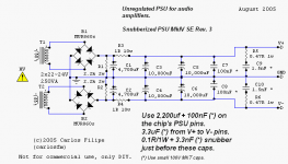
I'll also put 1W resistors for the snubbers, as it's what I've been using lately.
Hold on...
regal said:Still don't understand the T1 & T2. Is this really a single transformer with dual secondaries?
Yes.
Because the software didn't have the symbol, I had to put two trafos.
For the purpose, it's the same.
You can use two trafos, or one with dual independent secondaries.
You can even use a CT trafo with this PSU, with 4 diodes or a single diode bridge.
Carlos,
Just curious, pertaining to my post on the LM338 regulated thread about a multi-amped system, you reccomended a unregged PSU. Having read this thread (and feeling the wrath of 50 pages of information overload), I was wondering how component values would scale as the traffo's VA was increased. I think I have a few ideas, but I'm very very new to the scene and would really like to hear your opinions about it. As far as I can see, you would only need to increase the supply caps (and possibly power dissipation in resistors), but I don't feel I have a solid grasp on what would be their actual values.
Sorry for the Qs, but I don't really have spare parts to work with, so I'd like to get a design well-laid out before I start ordering and demolish my next paycheck. Thanks.
Carlos, if your design goal is continuous output power at max, you should also use appropiate resistor values and if those are chosen for music then lower values are OK.carlosfm said:Here it is.
I hope everyone is happy now. 😀
Carlos , if you want people to really understand your ideas I think some explanations are needed along with your schematics
Can't you edit your cad symbolscarlosfm said:Because the software didn't have the symbol, I had to put two trafos.
 How do you do when you want some part you don't have?
MikeLewis said:Carlos,
Just curious, pertaining to my post on the LM338 regulated thread about a multi-amped system, you reccomended a unregged PSU. Having read this thread (and feeling the wrath of 50 pages of information overload), I was wondering how component values would scale as the traffo's VA was increased. I think I have a few ideas, but I'm very very new to the scene and would really like to hear your opinions about it. As far as I can see, you would only need to increase the supply caps (and possibly power dissipation in resistors), but I don't feel I have a solid grasp on what would be their actual values.
Sorry for the Qs, but I don't really have spare parts to work with, so I'd like to get a design well-laid out before I start ordering and demolish my next paycheck. Thanks.
This PSU can cope with 3 chips, as I suggested you.
30,000~40,000uf capacitance after the series resistors is what I would use.
For the trafos, 400VA is fine.
peranders said:
Can't you edit your cad symbols
I use a free version of Circuit Maker.
I like the small and 'clean' schematics it produces.
But it's somewhat limited, and also I didn't think there would be confusion about the trafo... (?!)
peranders said:Carlos, if your design goal is continuous output power at max, you should also use appropiate resistor values and if those are chosen for music then lower values are OK.
That's what I did.
But I'm open to suggestions and ok, 10W series resistors it is.
It should handle 4 chips without any problem.
This is for a class B amp, and music has peaks, it's not a continuous tone.
Anyway, it's important to point out that the MUR860 diodes are fine for a couple of chips, but more than that one should use bigger diodes.
Hi Carlos, just thought I'd throw in a pic of my day's work 😉
An externally hosted image should be here but it was not working when we last tested it.
Vikash said:Hi Carlos, just thought I'd throw in a pic of my day's work 😉
An externally hosted image should be here but it was not working when we last tested it.
hehe that looks exactly like the schematic's layout...
Vikash said:Hi Carlos, just thought I'd throw in a pic of my day's work 😉
Cool. 😎
Oh btw, put the snubbers as close as possible to the last caps.
By your pic, if you bend the bypass caps to the other side of the big caps you'll get the space for the snubbers right next to them.
homer09 said:hehe that looks exactly like the schematic's layout...
Indeed.😀
Orion Speakers; Power Supply Suggestions
Evening All,
Thinking caps required (to interpret the long-winded question. I doubt much collective brain-power will be required for the answers however). I apologize for the wordy post.
My "grand project" is a pair of Linkwintz's Orion speakers. (*See below) I am just about to start putting together my eight LM3886 chipamps according to Carlos' latest version, but I would like some advice on how to "distribute my resources" in the unregulated power supply (also Carlos' latest verion).
I was going to have dual mono configuration, and I have 24 * 10,000 uF capacitors and 12 * 4700uF capacitors to play with.
I had thought that it might be best to have separate power supplies for the woofers' LM3886 chipamps and the midrange/tweeter LM3886 chipamps. The Woofers would have one Power Supply for each pair of LM3886 chipamps, i.e. ONE Power Supply (4 * 10 000uF + 2 * 4700uF capaictors); TWO LM3886 chipamps; TWO Woofers.
Question 1:
Is that sufficient capacitance for the two woofers, or should I beef it up by 50%?
The following questions relate to the Mid-range and Tweeter power supplies and amplification, and are asked to help me perhaps rationalize my space and component requirements.
***********************
There are two power supply arrangements possible for the amps for drive the mid-range and tweeter:-
Option (A) Make a separate power supply for a pair of LM3886 chipamps to drive the midrange and treble, i.e. ONE Power Supply; TWO LM3886 chipamps, TWO Drivers (one tweeter and one mid-range); OR
Option (B) Make one Power Supply for each amp and driver, i.e. TWO Power Supplies, TWO LM3886 chipamps, TWO Drivers (one tweeter and one mid-range).
Question 2:
Which of these options do you recommend, please?
***********************
(If I made Option (A), I was going to make a standard recipe Carlos Unregulated Power Supply: 4 * 10,000uF (plus 2 * 4700uF) capacitors.)
Question 3:
If I made Option (B), would 2 * 10 000uF capacitors be suitable for each power supply?
***********************
Question 4 - (regarding the 4700uF caps in Option B):
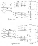
If I made Option B (with 2 * 10 000uF per power supply), which of the arrangements (of bridge, 4700uF capacitors and resistors) shown in the attachment would be better? I suspect Option B(ii) may be better if there is some "Carlos FM Magic" in the impedance matching between the MUR860's and the capacitors. (Apologies for the scanned picture, but it is the best I can readily do.)
***********************
Regards,
George Boles.
*For those of you not familiar with the Orion project, it comprises 4 actively crossed-over drivers per channel: SEAS Millennium tweeter (crossed over @ 1440 Hz); 8" SEAS magnesium-coned midrange (crossed over @ 120Hz); and 2 Peerless 10" XLS long throw woofers, each driver powered individually. (http://www.linkwitzlab.com/orion_challenge.htm#The challenge)
Evening All,
Thinking caps required (to interpret the long-winded question. I doubt much collective brain-power will be required for the answers however). I apologize for the wordy post.
My "grand project" is a pair of Linkwintz's Orion speakers. (*See below) I am just about to start putting together my eight LM3886 chipamps according to Carlos' latest version, but I would like some advice on how to "distribute my resources" in the unregulated power supply (also Carlos' latest verion).
I was going to have dual mono configuration, and I have 24 * 10,000 uF capacitors and 12 * 4700uF capacitors to play with.
I had thought that it might be best to have separate power supplies for the woofers' LM3886 chipamps and the midrange/tweeter LM3886 chipamps. The Woofers would have one Power Supply for each pair of LM3886 chipamps, i.e. ONE Power Supply (4 * 10 000uF + 2 * 4700uF capaictors); TWO LM3886 chipamps; TWO Woofers.
Question 1:
Is that sufficient capacitance for the two woofers, or should I beef it up by 50%?
The following questions relate to the Mid-range and Tweeter power supplies and amplification, and are asked to help me perhaps rationalize my space and component requirements.
***********************
There are two power supply arrangements possible for the amps for drive the mid-range and tweeter:-
Option (A) Make a separate power supply for a pair of LM3886 chipamps to drive the midrange and treble, i.e. ONE Power Supply; TWO LM3886 chipamps, TWO Drivers (one tweeter and one mid-range); OR
Option (B) Make one Power Supply for each amp and driver, i.e. TWO Power Supplies, TWO LM3886 chipamps, TWO Drivers (one tweeter and one mid-range).
Question 2:
Which of these options do you recommend, please?
***********************
(If I made Option (A), I was going to make a standard recipe Carlos Unregulated Power Supply: 4 * 10,000uF (plus 2 * 4700uF) capacitors.)
Question 3:
If I made Option (B), would 2 * 10 000uF capacitors be suitable for each power supply?
***********************
Question 4 - (regarding the 4700uF caps in Option B):
If I made Option B (with 2 * 10 000uF per power supply), which of the arrangements (of bridge, 4700uF capacitors and resistors) shown in the attachment would be better? I suspect Option B(ii) may be better if there is some "Carlos FM Magic" in the impedance matching between the MUR860's and the capacitors. (Apologies for the scanned picture, but it is the best I can readily do.)
***********************
Regards,
George Boles.
*For those of you not familiar with the Orion project, it comprises 4 actively crossed-over drivers per channel: SEAS Millennium tweeter (crossed over @ 1440 Hz); 8" SEAS magnesium-coned midrange (crossed over @ 120Hz); and 2 Peerless 10" XLS long throw woofers, each driver powered individually. (http://www.linkwitzlab.com/orion_challenge.htm#The challenge)
Attachments
With p2p I couldn't see any obvious alternative ways of wiring. I'd like to see how others have implemented this p2p if you have any pics...
Wait till you see the p2p amp. 😉
Wait till you see the p2p amp. 😉
Re: Orion Speakers; Power Supply Suggestions
Geez George... your post demands some time to answer. 😀
I'll do that tonight.
See ya later.
GeorgeBoles said:Evening All,
...
Geez George... your post demands some time to answer. 😀
I'll do that tonight.
See ya later.
Ok, here it goes...
4*10,000uf per rail, and 4,700uf before the 1R series resistor.
Option (B), even if you just use one trafo.
You can use less capacitance there.
After the first 4,700uf cap and 1R series resistor, use 3*4,700uf (or 2*6,800uf) per rail for the mid and 2*4,700uf (or 3*3,300uf) for the treble.
Lots of work to do there.
Enjoy. 😎
GeorgeBoles said:I had thought that it might be best to have separate power supplies for the woofers' LM3886 chipamps and the midrange/tweeter LM3886 chipamps. The Woofers would have one Power Supply for each pair of LM3886 chipamps, i.e. ONE Power Supply (4 * 10 000uF + 2 * 4700uF capaictors); TWO LM3886 chipamps; TWO Woofers.
4*10,000uf per rail, and 4,700uf before the 1R series resistor.
GeorgeBoles said:There are two power supply arrangements possible for the amps for drive the mid-range and tweeter:-
Option (A) Make a separate power supply for a pair of LM3886 chipamps to drive the midrange and treble, i.e. ONE Power Supply; TWO LM3886 chipamps, TWO Drivers (one tweeter and one mid-range); OR
Option (B) Make one Power Supply for each amp and driver, i.e. TWO Power Supplies, TWO LM3886 chipamps, TWO Drivers (one tweeter and one mid-range).
Question 2:
Which of these options do you recommend, please?
Option (B), even if you just use one trafo.
You can use less capacitance there.
After the first 4,700uf cap and 1R series resistor, use 3*4,700uf (or 2*6,800uf) per rail for the mid and 2*4,700uf (or 3*3,300uf) for the treble.
Lots of work to do there.
Enjoy. 😎
- Status
- Not open for further replies.
- Home
- Amplifiers
- Chip Amps
- The (high-cap.) unregulated PSU for chipamps