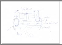
Joachim, am i reading that correctly, motor, bearing and arm all terminated on different levels?
I can't read the handwritten annotation but it looks to me like two layers; the upper one with the arm and bearing/platter and the lower with the motor (this is roughly the format my deck is built to).
Yes, it is a double sandwich with dampers in-between.
The arm and the motor are fixed to the softer material, the bearing and the feet to the harder.
The arm and the motor are fixed to the softer material, the bearing and the feet to the harder.
Joachim,
I am working on a very similar design, including sorbothane stoppers between sandwich layers, and sorbothane hemispheres underneath. However, I have two designs, one which has the arm fixed to the top plate of the turntable, and one where the arm sits on an arm pod which sits on the lower composite. Each composite is made from two pieces of 12.5mm thick mdf, which sandwiches a composite made of aluminium facings around a polyethylene core. All are stuck together with 1.1mm thick acrylic foam adhesive tape, (3M RP45).
Is this convergent thinking?😛
...the speed of sound
Can you explain how you define that term
Here we go ...
You will use an inverted bearing, correct? What platter - dur-aluminium?
Here we go ...
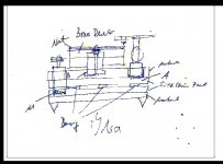
The JPG scales very bad, better post in PNG format.
Attachments
I wouldn't link the motor and arm.
They are not linked directly, the motor sits on the bottom layer.
Easier?
Yes, but it does not change anything about JPG's scaling badly 🙂
Ok Mr Fussy😀.
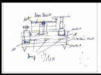
Is THIS better?😉
(both are from a PS source and on my Mac look identical - even when scaled!)
Is THIS better?😉
(both are from a PS source and on my Mac look identical - even when scaled!)
Attachments
Last edited:
Speed of sound in air is defined as ca. 343msec.
In solid material it is higher.
Say we have a paper cone in a loudspeaker.
We measure in the near field and find that the cone breaks up at a certain frequency, say 2kHz. We will see a peak at that frequency.
Now we coat that cone with lacquer. After the lacquer is dried we will see that the breakup has shifted up, say to 2.2kHz and when we have luck that peak will be minimized in level.
The speed of sound in the lacquered cone is then 10% higher then in the untreated cone.
I hope that makes it clear.
Joachim -
In your sketch do you have the arm interface on the 2nd layer of the top plinth? Are you trying for a small bit of isolation (as there will be some constrained layer damping between the two sheets of material) between the bearing well and the arm?
In general I like the layout. 🙂
In your sketch do you have the arm interface on the 2nd layer of the top plinth? Are you trying for a small bit of isolation (as there will be some constrained layer damping between the two sheets of material) between the bearing well and the arm?
In general I like the layout. 🙂
- Status
- Not open for further replies.
- Home
- Source & Line
- Analogue Source
- The Good Turntable