A Joke...at least that is the way I took it!! Quite funny actually!
Beautiful job....How does it sound? And the arm; any progress?
Beautiful job....How does it sound? And the arm; any progress?
I think the picture of the enormous tt platter, the size of a truck tire, had been removed.
Ah, I see - or rather, Ididn't see it 🙂
A Joke...at least that is the way I took it!! Quite funny actually!
Beautiful job....How does it sound? And the arm; any progress?
Yes, a joke, I just didn't understand it 🙂.
Many thanks (regarding the deck) - I'm very pleased with the sound, but then I have been working on it for a long time. I've not made much progress recently on the arm although I have built a working 'proof of concept' prototype and that seems to work well (some changes needed). It's quite a radical design and will be quite tricky to make. I've been making new armboards and most recently a new version of the magnetic bearing (also the record clamp and mat system).

sq225917 hears it quite regularly 🙂.
YNWOAN; that looks beautiful.
Thanks 🙂.
Last edited:
Great looking deck.
Could you give us a brief rundown of materials used etc
I'm trying to catch up after 30 odd yrs of not doing anything with the HiFi
Jay
Could you give us a brief rundown of materials used etc
I'm trying to catch up after 30 odd yrs of not doing anything with the HiFi
Jay
Could you give us a brief rundown of materials used etc
Hi and thanks.
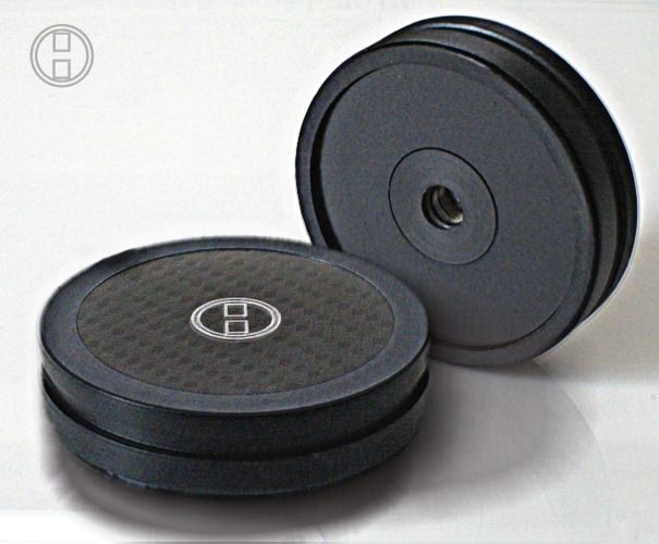
Briefly, it is a suspended design powered by an AC motor. The chassis is a laminate of carbon fibre and Nomex, dual layers depending on which component is attached. The armboard is a dual constrained layer (both layers are shaped differently) aluminium construction and couples to the chassis via clearly defined points. The bearing is a relatively traditional design but employs magnetic repulsion so there is no vertical load carried by the bearing shaft. The bearing is also of a high drag design which helps maintain a constant load on the motor and significantly improves pitch stability (drive is via a precision ground flat belt). The main chassis is split and contains a silicone damped sprung suspension. The stand is physically built in to the base and helps define areas of support (i.e. the motor pod attaches to a separate area/island. Although the chassis and armboard are quite low mass designs, the main plinth is quite high mass and this is what the suspension sees (the suspension cannot be seen in the picture - the three adjustment towers on the chassis are for fine adjustment and are how the sub-chassis interfaces with the main suspended plinth - they are not the main suspension elements). the motor is positioned at the 9 o'clock position and has adjustment for tilt and for record centre to drive pulley distance. It is built into a separate three point chuck type housing. The motor is an AC type and powered from an external power supply (not shown).
The armboard:

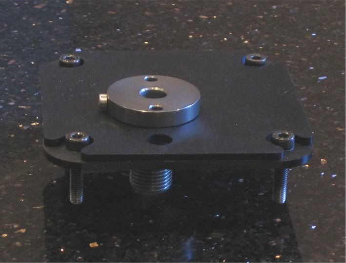
Oh, it has a lid too 🙂.
Last edited:
Good info are you useing a linn type motor/ control. Is the new mag lift very different? Is the arm a uni pivot ?
Am off to sunny Iceland in an hr so will catch up when I can
Jay
Am off to sunny Iceland in an hr so will catch up when I can
Jay
Good info are you useing a linn type motor/ control. Is the new mag lift very different? Is the arm a uni pivot ?
Am off to sunny Iceland in an hr so will catch up when I can
Jay
Am off to sunny Iceland in an hr so will catch up when I can
Jay
Good info are you useing a linn type motor
Yes
Is the new mag lift very different?
Is it very different than the magnetic bearing I was using previously? It's a development of that bearing rather than a radical departure. It's significantly smaller and the radiated field is much lower.
Is the arm a uni pivot ?
The arm in the picture is a Naim Aro which is a unipivot. The arm I am working on is also a unipivot but is otherwise quite different.
Hi and thanks.
Briefly, it is a suspended design powered by an AC motor. The chassis is a laminate of carbon fibre and Nomex, dual layers depending on which component is attached. The armboard is a dual constrained layer (both layers are shaped differently) aluminium construction and couples to the chassis via clearly defined points. The bearing is a relatively traditional design but employs magnetic repulsion so there is no vertical load carried by the bearing shaft. The bearing is also of a high drag design which helps maintain a constant load on the motor and significantly improves pitch stability (drive is via a precision ground flat belt). The main chassis is split and contains a silicone damped sprung suspension. The stand is physically built in to the base and helps define areas of support (i.e. the motor pod attaches to a separate area/island. Although the chassis and armboard are quite low mass designs, the main plinth is quite high mass and this is what the suspension sees (the suspension cannot be seen in the picture - the three adjustment towers on the chassis are for fine adjustment and are how the sub-chassis interfaces with the main suspended plinth - they are not the main suspension elements). the motor is positioned at the 9 o'clock position and has adjustment for tilt and for record centre to drive pulley distance. It is built into a separate three point chuck type housing. The motor is an AC type and powered from an external power supply (not shown).
The armboard:
Oh, it has a lid too 🙂.
Very nice work, I guess you have an access to a machine shop.
Thanks for posting the pictures. Maybe you could show more. I would be also interested of the levitation stuff, since I don't know anything about it.
You mean the one in post #140, or did I miss some Valuable Image in this thread?I think the picture of the enormous tt platter, the size of a truck tire, had been removed.
Hi and thanks.
Briefly, it is a suspended design powered by an AC motor. The chassis is a laminate of carbon fibre and Nomex, dual layers depending on which component is attached. The armboard is a dual constrained layer (both layers are shaped differently) aluminium construction and couples to the chassis via clearly defined points. The bearing is a relatively traditional design but employs magnetic repulsion so there is no vertical load carried by the bearing shaft. The bearing is also of a high drag design which helps maintain a constant load on the motor and significantly improves pitch stability (drive is via a precision ground flat belt). The main chassis is split and contains a silicone damped sprung suspension. The stand is physically built in to the base and helps define areas of support (i.e. the motor pod attaches to a separate area/island. Although the chassis and armboard are quite low mass designs, the main plinth is quite high mass and this is what the suspension sees (the suspension cannot be seen in the picture - the three adjustment towers on the chassis are for fine adjustment and are how the sub-chassis interfaces with the main suspended plinth - they are not the main suspension elements). the motor is positioned at the 9 o'clock position and has adjustment for tilt and for record centre to drive pulley distance. It is built into a separate three point chuck type housing. The motor is an AC type and powered from an external power supply (not shown).
The armboard:
Oh, it has a lid too 🙂.
Judging for your text, we now understand how heavily you have been involved with this project. I really apreciate your knowledge that coincides with some of the most important statements in this thread.
Maybe you could pour some hints so we could jump ahead faster.
We all agreed on a heavy platter and special maglev... (we are waiting for an inovative magnetic attraction system to be drawn)... I personally am in favor of AC motor but know little about it (My choice is based on subjective listening impressions).
You seem to have really precise ideas on how to make the plinth and decoupling suspension... maybe you would care to share 🙂
I started a thread on this forum about five years ago when I first started experimenting with magnetically supporting the platter/bearing - I believe that thread is still active and many have gone on to implement some version of the bearing. Conceptually the idea is very simple, magnets in opposition (not attraction). Some have chosen to use the magnets to alleviate load on the thrust pad but I choose to completely support the platter.
As you say, I have quite precise ideas regarding turntables and the chances are that some of them will not be in line with those of others. For example, I'm not a supporter of heavy platters. high mass, in itself, does not guarantee speed stability. In addition, high mass platters can cause significant side loads on the main bearing if the platter is not precisely balanced and absolutely level. Finally, I do not believe that they act as an energy sink. The role of each component should be looked at and rationalised. Part of the problem with turntables is that there are relatively few components and often these components are expected to do more than one job. for example,the platter is part of the drive system, It also loads the chassis and it also terminated the record - it may also be expected to govern the motor by being a fly wheel and yet maintain absolutely fixed rotational velocity. I believe that some of these roes are at odds with each other. The turntable must be viewed as a whole and how parts interact must be considered, One cannot just cherry pick ideas that appeal and expect them to work together. The platter bearing, belt, motor and suspension all interact together to create a system - making an improvement to one element will not necessarily make the system better if it is at odds with the whole. For example, I found that supporting the platter magnetically reduced bearing noise and friction. Whilst reducing noise was good, it transpired that reducing the friction was actually bad as it reduced the load on the motor and this caused the motor torque to be less stable. Many turntables do not, in my opinion, sufficiently consider the interaction of the motor, platter mass, bearing and belt. One must decide which is leading and which is following. In my deck, the motor leads and the platter is subservient to that. The idea that the motor has sufficient torque to overcome the the static load of the platter but when running will momentarily allow the platter to govern it is inherently flawed. Also, one must look at the actual torque characteristics of the motor during normal play as opposed to startup. At startup the static load is high and torque is high, but when running friction levels are very low and very little energy is required to maintain momentum, as such, torque drops steeply to the point where record load can be significant.
As you say, I have quite precise ideas regarding turntables and the chances are that some of them will not be in line with those of others. For example, I'm not a supporter of heavy platters. high mass, in itself, does not guarantee speed stability. In addition, high mass platters can cause significant side loads on the main bearing if the platter is not precisely balanced and absolutely level. Finally, I do not believe that they act as an energy sink. The role of each component should be looked at and rationalised. Part of the problem with turntables is that there are relatively few components and often these components are expected to do more than one job. for example,the platter is part of the drive system, It also loads the chassis and it also terminated the record - it may also be expected to govern the motor by being a fly wheel and yet maintain absolutely fixed rotational velocity. I believe that some of these roes are at odds with each other. The turntable must be viewed as a whole and how parts interact must be considered, One cannot just cherry pick ideas that appeal and expect them to work together. The platter bearing, belt, motor and suspension all interact together to create a system - making an improvement to one element will not necessarily make the system better if it is at odds with the whole. For example, I found that supporting the platter magnetically reduced bearing noise and friction. Whilst reducing noise was good, it transpired that reducing the friction was actually bad as it reduced the load on the motor and this caused the motor torque to be less stable. Many turntables do not, in my opinion, sufficiently consider the interaction of the motor, platter mass, bearing and belt. One must decide which is leading and which is following. In my deck, the motor leads and the platter is subservient to that. The idea that the motor has sufficient torque to overcome the the static load of the platter but when running will momentarily allow the platter to govern it is inherently flawed. Also, one must look at the actual torque characteristics of the motor during normal play as opposed to startup. At startup the static load is high and torque is high, but when running friction levels are very low and very little energy is required to maintain momentum, as such, torque drops steeply to the point where record load can be significant.
I did some really crazy experiments tonight. sq had send me a PM with a photo that showed a small diameter carbon fiber disk that floats 2/3rd of the record ca. 1 - 2mm over the platter so it does not touch it. That was the result of research a friend of him did that tried all kinds of platter mats.
I am that friend that sq described. I have indeed tried a lot of different ways to terminate/support a record. I won't list them all, but a lot of compliant and non-compliant materials - including a number of graphite mats and even a whole graphite platter. My conclusion is that it is not only important how you support the record but what material you support it on and how compliant that support is - altering any one of these elements will impact on the sound.
The same can be said for how the arm is terminated.
Many turntables fail to consider these issues adequately in my opinion and often focus on one specific goal.
No, didn't even take picture of most of them (I did start about 15 years ago 🙂) - still got some though - glass, felt, cork (big and little) - sold the acrylic and composite cork ones, some foam ones, got the graphite one and the platter and the two different small graphite ones.
- Status
- Not open for further replies.
- Home
- Source & Line
- Analogue Source
- The Good Turntable