Lumba Ogir said:roender,
pretty nice design but what are R12/13 doing there?
Thank you.
Dis you read all posts in that thread? There are no so many ...
http://www.diyaudio.com/forums/showthread.php?postid=1146544#post1146544
Lumba,
You and I appear to hold similar views; however, don't underestimate either Pete or Mihai - I have watched with astonishment how quickly Pete has picked this stuff up through his simulations, far outstripping me..... and I have corresponded with Mihai and know his mathematical insights to be profound and accurate.
Loading down the VAS to 'swamp' the output stage drive variations is not such a bad idea, and it is a clever way to minimise the lag compensation even if it does throw away some of the OLG.
I'm not contributing here, but I have designed some very good sounding amps, and I salute Peter's efforts. Mind you, he should come to me for a decent pcb layout, but that's another matter.
Hugh
Yes , it might be, but a reversable oneBy roender - Loading the VAS with resistors to ground is a big mistake.
so on the real thing, I will try with and
without.
I have no idea how they would sound in real life,butby lumba - They do but may favourably affect the sound in real life.
on LTspice 4 they totally "choke" amp off >2mhz and change
the unity gain plot.. so I assume the real world would reflect this.
ahh , one I didn't know about ....will read ,thanks🙂Tests was made with "Symasym - roender style"
OS
BTW.. Since you guys have experience with this topology,do
you consider it unstable. ? I see no evidence to support this
at least in simulation.
ostripper said:
BTW.. Since you guys have experience with this topology,do
you consider it unstable. ? I see no evidence to support this
at least in simulation.
Well, with your output stage is stable. Do not try triple EF unless you are a grand master in PCB design
And boy do I have enough OLG... almost 9 Db more than FA1By Aksa - Loading down the VAS to 'swamp' the output stage drive variations is not such a bad idea, and it is a clever way to minimise the lag compensation even if it does throw away some of the OLG.
Thanks for comment, totally opposite "you know who" as he
talks down to me but only drives me further onward.(bootstrap thread)
😡 he finally got to me.. I will not allow "threadstalking"
here anymore and will boldly oppose it..

I would welcome that, hugh.. but I have no printer . All of doug selfs general layout rules includingBy Aksa - I'm not contributing here, but I have designed some very good sounding amps, and I salute Peter's efforts. Mind you, he should come to me for a decent pcb layout, but that's another matter.
NFB takeoff, grounding, short traces between stages,separated
OP and input stages,etc. (both
yours and mine break rules with rails on opposite sides😀)
I could still make minor changes now (as i have not etched them yet) short of a major overhaul..
BTW - All those jumpers in OPS at top of board form 18ga solid
wire "rails" and save on a lot of foil (sony/sanyo HT receiver "trick")allows for 4-way use of board (sandwich.90 and 180,or as driver board)
An externally hosted image should be here but it was not working when we last tested it.
OS
roender,
removing those resistors (100kOhm) cannot give "a major sonical improvement", they are in no way that detrimental. THD will necessarily rise, but I do not agree with your spectrum analysis.
Dear Hugh,
nice to meet you. I just want to greet you. Maybe I should be more wordy.
removing those resistors (100kOhm) cannot give "a major sonical improvement", they are in no way that detrimental. THD will necessarily rise, but I do not agree with your spectrum analysis.
Dear Hugh,
nice to meet you. I just want to greet you. Maybe I should be more wordy.
Lumba,

I don't get it ... do you want to tell me what I've heard, and not only me but some of my friends?
Make the test yourself an see how it sound.
Just the facts man, just the facts ...
Mihai
I don't get it ... do you want to tell me what I've heard, and not only me but some of my friends?
Make the test yourself an see how it sound.
Just the facts man, just the facts ...
Mihai
roender,
I don`t argue your subjective judgment, just wish to mention aggravatingly, that not seldom much lower values are used for desired results.
I don`t argue your subjective judgment, just wish to mention aggravatingly, that not seldom much lower values are used for desired results.
ostripper said:Here they are..MJL
Sometimes something is right in front of me, and I still don't see it...😱
Thanks. 🙂
ostripper said:
BTW, I had no problem modeling the symasym after giving it
matched Cdoms (same as mine, elliots has no Cdom)
just to see how/why it worked.
OS
I tried the second Miller cap (100pF) on my sim, but it didn't completely stabilize it.
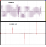
Does LT have a real time o-scope? If so, probe the output from the LTP into the VAS. Here's what I see for the stock Symasym (on top) and the most well behaved amp that I have modeled so far - the RMI by roender. This is with both amps handling a 1k squarewave.
Attachments
AKSA said:
I have watched with astonishment how quickly Pete has picked this stuff up through his simulations, far outstripping me..... and I have corresponded with Mihai and know his mathematical insights to be profound and accurate.
OS came in here with some knowledge, for sure, but he's moving by leaps and bounds. He's picking this stuff up fast.

Roender has designed an amp, the RMI amp, and if it were a woman it would be a very, VERY sexy woman. 😀

Hello ostripper.
I would not change very much from this schematic
from December 1
http://i302.photobucket.com/albums/nn112/ostripper/frugal/FA2bestsim.jpg
Have you thought about using a separate Transformer/supply for the Output Stage. = for the drivers+power transistors?
You know, simulations uses ideal voltage sources.
In real life there are no such things 😀
VAS and input stage should benefit a lot from there own 'clean supply'.
Preferably like ~5 Volt higher than output
-----------------------------------------------
I am not sure about the 'base stopper' resistors.
Should they be at BASE of the output transistors? Or like now 47 Ohms at drivers?
-----------------------------------------------
About the 68k R11/R12 resistors.
I think you should experiment with values. In the real amplifier.
Changing these in values can make a lot of difference!
There is a sweet spot to find ....
-----------------------------------------------
About Q6, the cascode in VAS.
Here is an old idea I posted to quasi in January 2006.
Even if you are using a current mirror, it may be worth a try to connect the cascoding transistor Q6 to follow the voltage of the Vbe multiplier.
(Of course the vas transistors have to take the Vce in question)
Let's see what you find out, ostripper 🙂
Lineup 🙂 Regards
http://www.diyaudio.com/forums/attachment.php?s=&postid=810128&stamp=1136798176
Lineup Idea post:
http://www.diyaudio.com/forums/showthread.php?postid=810128#post810128
I would not change very much from this schematic
from December 1
http://i302.photobucket.com/albums/nn112/ostripper/frugal/FA2bestsim.jpg
Have you thought about using a separate Transformer/supply for the Output Stage. = for the drivers+power transistors?
You know, simulations uses ideal voltage sources.
In real life there are no such things 😀
VAS and input stage should benefit a lot from there own 'clean supply'.
Preferably like ~5 Volt higher than output
-----------------------------------------------
I am not sure about the 'base stopper' resistors.
Should they be at BASE of the output transistors? Or like now 47 Ohms at drivers?
-----------------------------------------------
About the 68k R11/R12 resistors.
I think you should experiment with values. In the real amplifier.
Changing these in values can make a lot of difference!
There is a sweet spot to find ....
-----------------------------------------------
About Q6, the cascode in VAS.
Here is an old idea I posted to quasi in January 2006.
Even if you are using a current mirror, it may be worth a try to connect the cascoding transistor Q6 to follow the voltage of the Vbe multiplier.
(Of course the vas transistors have to take the Vce in question)
Let's see what you find out, ostripper 🙂
Lineup 🙂 Regards
lineup said:this is an old idea I have had, but havent tried yet
I have attached a drawing using bipolar
It is another attempt to 'cascoding' VAS pair in this type of N-Channel amps
to give this pair equal working condition
Workhorse said:Well said LINEUP, this type of implementation is already in use with ECLER N-Channel amps www.ecler.com and also we use it exclusively...very good response
K a n w a r
Lineup Idea schematic:MikeB said:I ran some simulations in openloop,
the cascode configuration lineup has posted performed best, the .....
Mike
http://www.diyaudio.com/forums/attachment.php?s=&postid=810128&stamp=1136798176
Lineup Idea post:
http://www.diyaudio.com/forums/showthread.php?postid=810128#post810128
Sqauredance (nice)
Interesting, as I never gave the original symasym a dirty
sqaurewave before moving on to mine ..just an idea
to improve upon.
Here is that LTP to VAS pulse from FA2, looks like roenders..
To get real ,I did the next shot at 20Khz/.25v input for this output..
[ "gross compensation" at VAS output seems to round corners
of square more ,looking like my bootstrap simulation]
Slightly rounded rising edge, with 22pf cdom it just started to overshoot, but at full 70vp-p only .5us (100+ v slew)
balanced throughout, real
low Cdom (33p,with 22p I crashed sim) , no other compensation. this amp seems to stay stable and gets faster (slew)with
just a unity gain shift (here at 1mhz)..
[dark blue -output /green-yellow..VAS/L.blue- purple LTP]
One last sim before I etch it,
Both halves of the LTP Re...very symmetrical , all frequencies
all output levels ,current levels are locked as well 1.8Ma LTP
8.5Ma VAS , I think these are the most linear regions in
my device choices (device Hfe specs confirm this).
besides the widlar buffer and MJL's 2SA/C devices.
is important. Also, I "spike" my voltage sources with 5vAC
(2 frequencies to make them out of phase )
when doing simulations.
OS
By MJL - I tried the second Miller cap (100pF) on my sim, but it didn't completely stabilize it
Interesting, as I never gave the original symasym a dirty
sqaurewave before moving on to mine ..just an idea
to improve upon.
Here is that LTP to VAS pulse from FA2, looks like roenders..
An externally hosted image should be here but it was not working when we last tested it.
To get real ,I did the next shot at 20Khz/.25v input for this output..
An externally hosted image should be here but it was not working when we last tested it.
[ "gross compensation" at VAS output seems to round corners
of square more ,looking like my bootstrap simulation]
Slightly rounded rising edge, with 22pf cdom it just started to overshoot, but at full 70vp-p only .5us (100+ v slew)
An externally hosted image should be here but it was not working when we last tested it.
balanced throughout, real
low Cdom (33p,with 22p I crashed sim) , no other compensation. this amp seems to stay stable and gets faster (slew)with
just a unity gain shift (here at 1mhz)..
An externally hosted image should be here but it was not working when we last tested it.
[dark blue -output /green-yellow..VAS/L.blue- purple LTP]
One last sim before I etch it,
An externally hosted image should be here but it was not working when we last tested it.
Both halves of the LTP Re...very symmetrical , all frequencies
all output levels ,current levels are locked as well 1.8Ma LTP
8.5Ma VAS , I think these are the most linear regions in
my device choices (device Hfe specs confirm this).
about Q6 , its addition is what really made this VAS "tight",By lineup - About Q6, the cascode in VAS.
besides the widlar buffer and MJL's 2SA/C devices.
thats why a good CCS/w those extra caps (low PSRR)You know, simulations uses ideal voltage sources.
is important. Also, I "spike" my voltage sources with 5vAC
(2 frequencies to make them out of phase )
when doing simulations.
OS
One must not abuse those expensive components
, even in a prototype.Thank you for your CCS tip,
getting rid of D. selfs "evil" resistor, that design change works very well.
OS
, even in a prototype.Thank you for your CCS tip,
getting rid of D. selfs "evil" resistor, that design change works very well.
OS
Hi OS,
I complement you on a fine job here. I have taken the time to sim this and WOW it looks good.
It is (according to my sim) head and shoulders over the Symasym - performance and stability. THD is certainly low enough, with the 2nd stronger than the 3rd, with the higher order out of the picture (though to give roender credit, the 3rd and especially the 5th order harmonics jumped up with your "gross compensation" - might want to chop that).
I'm tempted to do a layout for this for myself. Having spent the time to do roender's RMI for my own use (reception to my "tampering" with his design and layout has been, shall we say, "cold" 🙂 ), and seeing performance from yours on a par with his much more complicated amp, it's probably worth my time.
Excellent work.
I just want to build it, but ,here in the "atomic city" (oakridge/
Knoxville, TN) NO ETCHANT....😡 😡 not even at radio
shack.
Is the urban legend of muriatic acid (HCL)/peroxide a
good substitute??
OS
OS
Knoxville, TN) NO ETCHANT....😡 😡 not even at radio
shack.
Is the urban legend of muriatic acid (HCL)/peroxide a
good substitute??
OS
Feel free to do it ..."warm" reception here.I'm tempted to do a layout for this for myself. Having spent the time to do roender's RMI for my own use
OS

Can you use the "muriatic" that they sell in home improvement stores.(33% HCL + 66%H2O)???
Does it have to be warm??
does it undercut worse than ferric cloride?
how long to etch a board.
OS
Does it have to be warm??
does it undercut worse than ferric cloride?
how long to etch a board.
OS
The one I use is 32% (on the label).
It will warm up on it's own when it starts to work. 🙂
I have done traces as thin as .1mm so undercut isn't a problem. Just don't leave it any longer than you need to.
It takes 5 minutes or so, depends upon how much solution you have and the size of the board/thickness of copper.
I read that you don't have a laser printer. If you want to send a layout file in pdf to me I'd gladly print out a sheet for you and send it off.
- Status
- Not open for further replies.
- Home
- Amplifiers
- Solid State
- The Frugalamp by OS